Exposed lens retroreflective article
a retroreflective article and lens technology, applied in the field of exposed lens retroreflective articles, can solve the problems of retroreflective nature of articles, and achieve the effect of low flash poin
- Summary
- Abstract
- Description
- Claims
- Application Information
AI Technical Summary
Benefits of technology
Problems solved by technology
Method used
Image
Examples
examples
Materials and Methods
[0088]All chemicals utilized herein were utilized as received without purification or further processing unless noted otherwise. The chemicals were obtained as noted below. Ancamine K-54 (catalyst) was obtained from Air Products and Chemicals, Inc. (Allentown, Pa.). Bayhydrol XP2470 (polyurethane dispersion), Bayhydrol® VPLS 2058, Desmodur® 2655 (diisocyanate polymer), Desmodur® NZ1 (hexamethylene diisocyanate (HDI) and isopohorone diisocyanate (IPDI) resin), and Desmophen® (hydroxyl-bearing polyester) were obtained from Bayer MaterialScience LLC (Pittsburgh, Pa.). BiCat® 8108a bismuth (Bi) catalyst was obtained from Shepherd Chemical Company (Norwood, Ohio). CAB-O-JET® 250C (a cyan pigment dispersion) and CAB-O-JET® 300 (a black pigment dispersion) were obtained from Cabot Corporation (Boston, Mass.). Dow Corning® Z-6011 silane was obtained from Dow Corning, Inc. (Midland, Mich.). Dynasylan® 1122 (silane) was obtained from Evonik Industries AG (Essen, Germany)....
examples 1 and 2
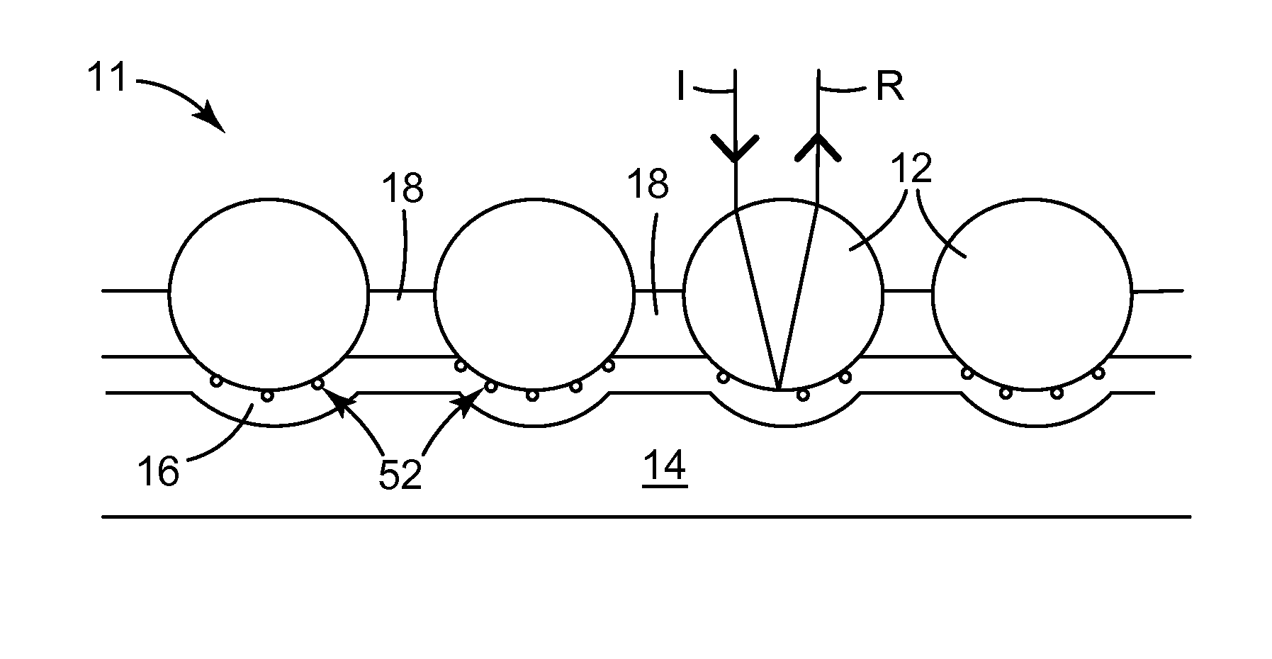
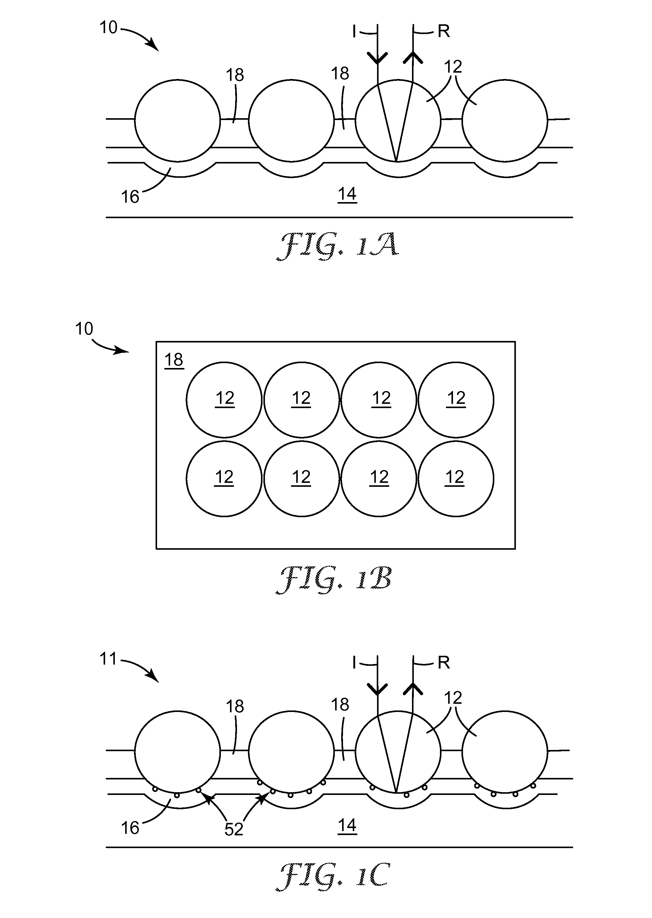
[0090]Paper having a weight of 220 g / m2 was coated (at a coating weight of 20 g / m2) with a layer of polyethylene adhesive. The article that included the paper and the adhesive is an example of the carrier web 32, seen in FIG. 4, which is made up of the paper (carrier 36) and the polyethylene (heat softenable adhesive 34). The adhesive coated paper was pre heated at 165° C. for about 1 minute, then a quantity of ceramic beads (diameter of about 60 um) were poured thereon to cover the entire surface of the adhesive coated paper. The article was then heated for an additional 2 minutes to allow the beads to sink about half way (about half the diameter of the beads sunk in) into the adhesive to form a layer of beads. The sheet was then cooled to room temperature, and any loose beads were removed with a vacuum. The article at this stage is an example of optical elements 12 embedded in a heat softenable adhesive 34 on a carrier 36.
[0091]A cyan color composition (Example 1—Bayhydrol® VPLS 2...
examples 3 through 7
[0099]Optical elements embedded in a heat softenable polymer on a carrier were made as described in Examples 1 and 2.
[0100]Color compositions as seen in Table 2 below were coated on the beads to form colored layers as described in Examples 1 and 2. The coating weight of the color composition was about 10 g / m2.
[0101]
TABLE 2Example 3Example 4Example 5Example 6Example 7% wt% wt% wt% wt% wtin wetin wetin wetin wetin wetformulaformulaformulaformulaformulaJ-color12.0515.0118.0721.0624.15JCF10DDesmophen9.297.295.313.271.28670Desmodur6.675.344.052.711.39NZ1Dynasylan0.850.850.860.850.841122Bichat0.010.010.010.010.018108CX1001.211.501.812.112.42Toluene34.9635.0034.9434.9934.95Ethyl34.9635.0034.9434.9934.95acetatetotal100.00100.00100.00100.00100.00
[0102]An aluminum coating, binder layer, and substrate were formed on the samples as described in Examples 1 and 2. The substrate was removed after 12 hours (as in Examples 1 and 2) and then the samples were tested. Examples 3 through 7 were tested w...
PUM
| Property | Measurement | Unit |
|---|---|---|
| thickness | aaaaa | aaaaa |
| size | aaaaa | aaaaa |
| flash point | aaaaa | aaaaa |
Abstract
Description
Claims
Application Information
 - R&D
- Intellectual Property
- Life Sciences
- Materials
- Tech Scout
- Unparalleled Data Quality
- Higher Quality Content
- 60% Fewer Hallucinations
Browse by: Latest US Patents, China's latest patents, Technical Efficacy Thesaurus, Application Domain, Technology Topic, Popular Technical Reports.
© 2025 PatSnap. All rights reserved.Legal|Privacy policy|Modern Slavery Act Transparency Statement|Sitemap|About US| Contact US: help@patsnap.com


