
Method for controlling an exhaust gas temperature

a technology of exhaust gas and temperature control, which is applied in the direction of electric control, machines/engines, instruments, etc., can solve the problems of low exhaust gas temperature during motoring and light engine braking, inability to work with nox reduction systems, and interruption of regeneration of particulate filters, so as to reduce the overall emissions of the vehicle, reduce the exhaust cleaning efficiency, and achieve sufficient efficiency

Active Publication Date: 2014-09-30
VOLVO LASTVAGNAR AB
View PDF11 Cites 7 Cited by
  • Summary
  • Abstract
  • Description
  • Claims
  • Application Information

AI Technical Summary

Benefits of technology

The patent describes a method for controlling the temperature of exhaust gas from an engine to ensure that the aftertreatment system operates properly. This method can be used in vehicles with both hybrid and non-hybrid transmissions. It involves alternating between two modes: one for providing high brake torque and another for generating lower brake torque using exhaust gas recirculation. This allows for engine braking while maintaining a high temperature in the exhaust gas system. The method also includes disengaging the engine from the driveline and reducing air flow through the exhaust gas system to further increase efficiency and reduce emissions. The patent also introduces a vehicle that utilizes this method.

Problems solved by technology

The exhaust gas temperature during motoring and light engine braking are so low that NOx reduction system will not work until it is heated up again.
Regeneration of particulate filters is interrupted and NO2-based regeneration of particulate filters will not work until it is heated up again.
The rather large thermal masses of the catalytic converters makes them expensive and difficult to heat up at low average load on the engine.
The motoring working point will not cool down the exhaust gas aftertreatment system due to extremely low mass flow.

Method used


Image

  • Method for controlling an exhaust gas temperature
  • Method for controlling an exhaust gas temperature
  • Method for controlling an exhaust gas temperature

Examples


Embodiment Construction

[0019]In the drawings, equal or similar elements are referred to by equal reference numerals. The drawings are merely schematic representations, not intended to portray specific parameters of the invention. Moreover, the drawings are intended to depict only typical embodiments of the invention and therefore should not be considered as limiting the scope of the invention.

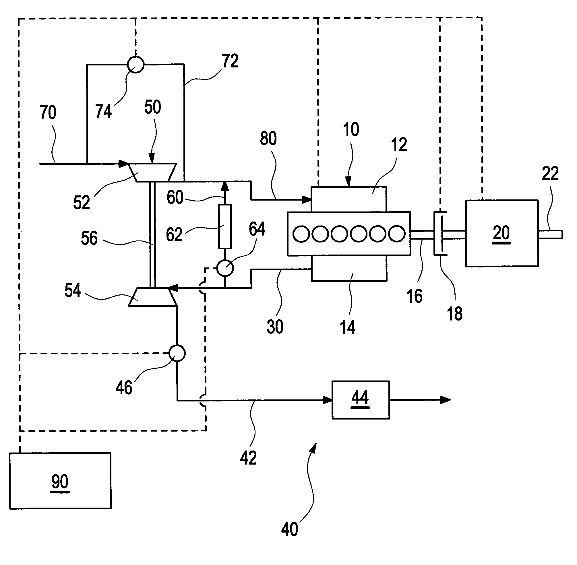
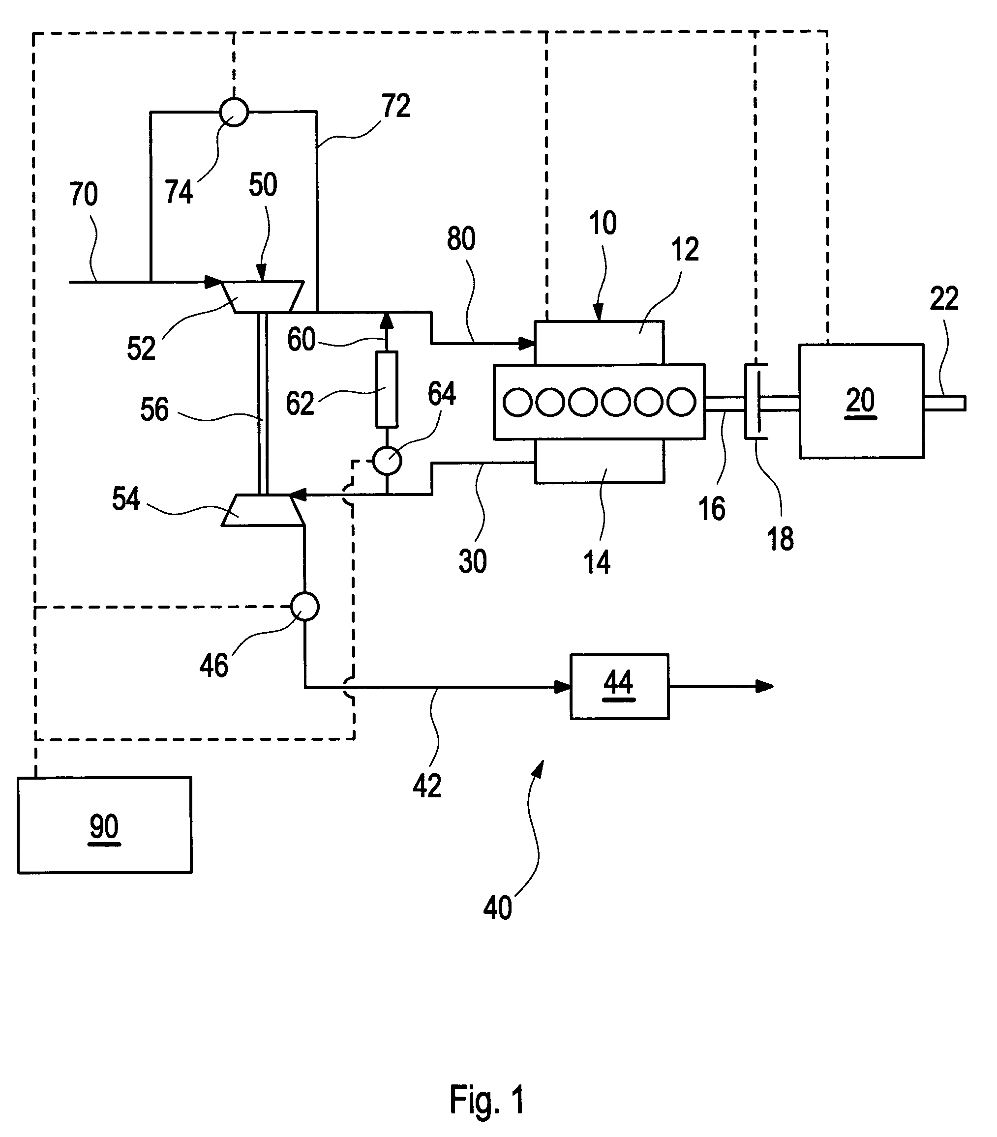
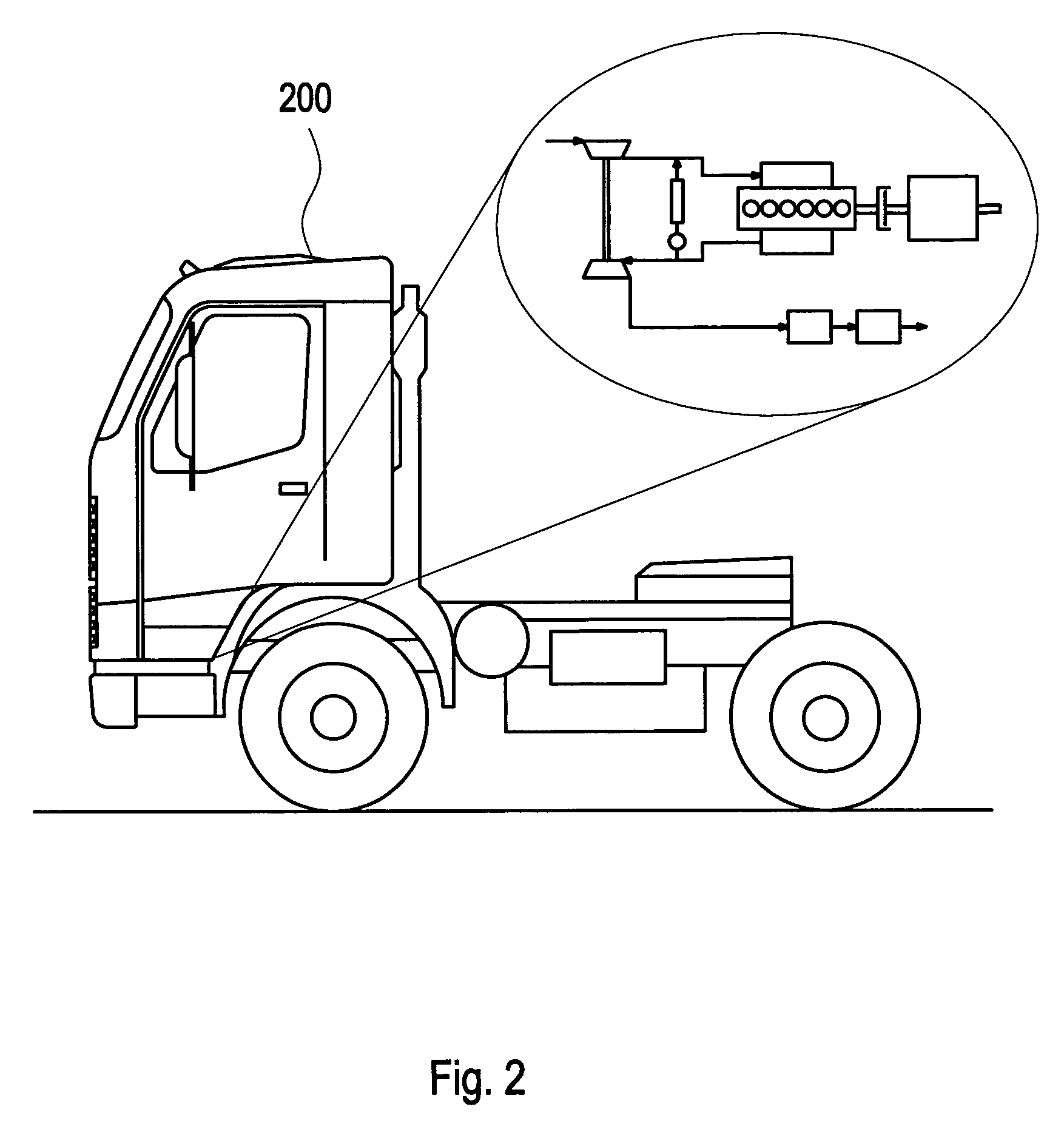
[0020]FIG. 1 depicts schematically an example embodiment of an arrangement comprising a combustion engine 10 and an exhaust gas aftertreatment system 40 which is operated with a method according to the invention. FIG. 2 displays a vehicle 200 employing the method. The vehicle 200 is preferably a light, medium of heavy duty vehicle such as a truck.

[0021]The engine 10 comprises an intake manifold 12 for air compressed by a compressor 52 of a turbocharger 50 and fed via air pipe 80 and an exhaust manifold 14 for discharging exhaust gases to a turbine 54 of the turbocharger 50 via an exhaust pipe 30 and the exhaust gas a...


PUM


Abstract

A method is provided for controlling an exhaust gas temperature of an engine of a vehicle during interruption of fuel supply to the engine, wherein the engine drives a driveline of the vehicle. The method involves alternating between two or more operational modes, wherein at least one of the operational modes maintains a higher exhaust temperature than the one or more other operational modes.

Description

BACKGROUND AND SUMMARY[0001]The invention relates to a method for controlling an exhaust gas temperature, particularly in a commercial vehicle comprising a diesel engine.[0002]The future legislation for heavy duty diesel engines requires an exhaust gas aftertreatment system for emission reduction. Both particulate filters and NOx reduction Systems needs elevated exhaust gas temperatures of about 250° C. to 350° C. for providing a reasonable efficiency in NOX conversion and soot removal, respectively. The exhaust gas temperature during motoring and light engine braking are so low that NOx reduction system will not work until it is heated up again. Regeneration of particulate filters is interrupted and NO2-based regeneration of particulate filters will not work until it is heated up again. Several methods are known in the art to increase the exhaust gas temperatures under certain driving conditions, for instance by burning additional fuel for heating up the exhaust gas temperature. In...

Claims


Application Information

Patent Timeline
Patent Type & Authority Patents(United States)
IPC IPC(8): F02D17/04F02D17/00F02D41/00F02D41/02F02D41/12F02M25/07
CPCF02M25/0707F02D41/0245F02D41/123F02D41/0055F02D2250/18Y02T10/26Y02T10/47F02M25/0727F02B3/06F02D13/04F02M26/05F02M26/10F02M26/23Y02T10/12Y02T10/40
Inventor LARSSON, PERALM, CHRISTERBERNLER, HANS
Owner VOLVO LASTVAGNAR AB
Learn More