
Cutting insert having a chip deflector

a technology of deflector and cutting edge, which is applied in the direction of shaping cutter, tool workpiece connection, manufacturing tools, etc., can solve the problems of quality, lack of homogeneity of mechanical properties, coefficient of thermal expansion, etc., and achieve the effect of improving lubrication of cutting edge and increasing pressur

Active Publication Date: 2014-09-09
SAFETY SA
View PDF78 Cites 0 Cited by
  • Summary
  • Abstract
  • Description
  • Claims
  • Application Information

AI Technical Summary

Benefits of technology

The cutting insert described in this patent is compact, as it does not require a clamping hole, and it prevents chips from reaching the traveling member (like a screw or bearing) that would normally be affected by the chips. The insert also has a deflecting surface that splits chip into smaller strips, which are easier to eject. The tool holder is also protected from chip damage. Lubrication for the cutting edges is achieved through a nozzle, which provides higher pressure to remove chips from the edge.

Problems solved by technology

The manufacture of cutting inserts having a through hole for a positioning and clamping screw nevertheless raises problems of quality.
During sintering, this non-homogeneity of the density of the material leads to a lack of homogeneity of mechanical properties, such as coefficient of thermal expansion.
Now, a cutting insert is subject to large amplitude thermal cycles during use.
Another problem is the fact that chips, which are sliding backwardly over a rake face forming a front edge of the upper face, originating from a leading cutting edge bounding this rake face, strike the top of the screw head and damage in particular the slot or equivalent recess for screwing.

Method used


Image

  • Cutting insert having a chip deflector
  • Cutting insert having a chip deflector
  • Cutting insert having a chip deflector

Examples


Embodiment Construction

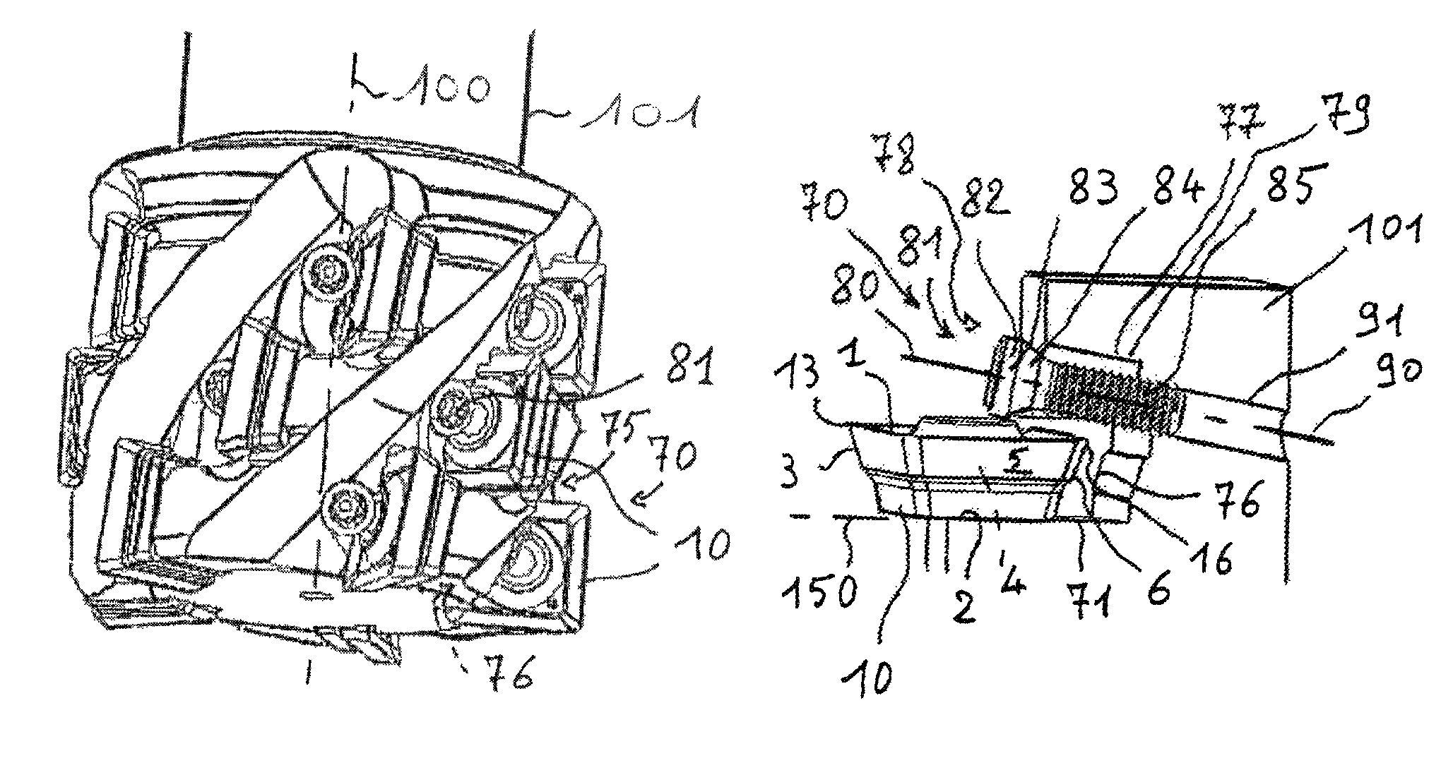
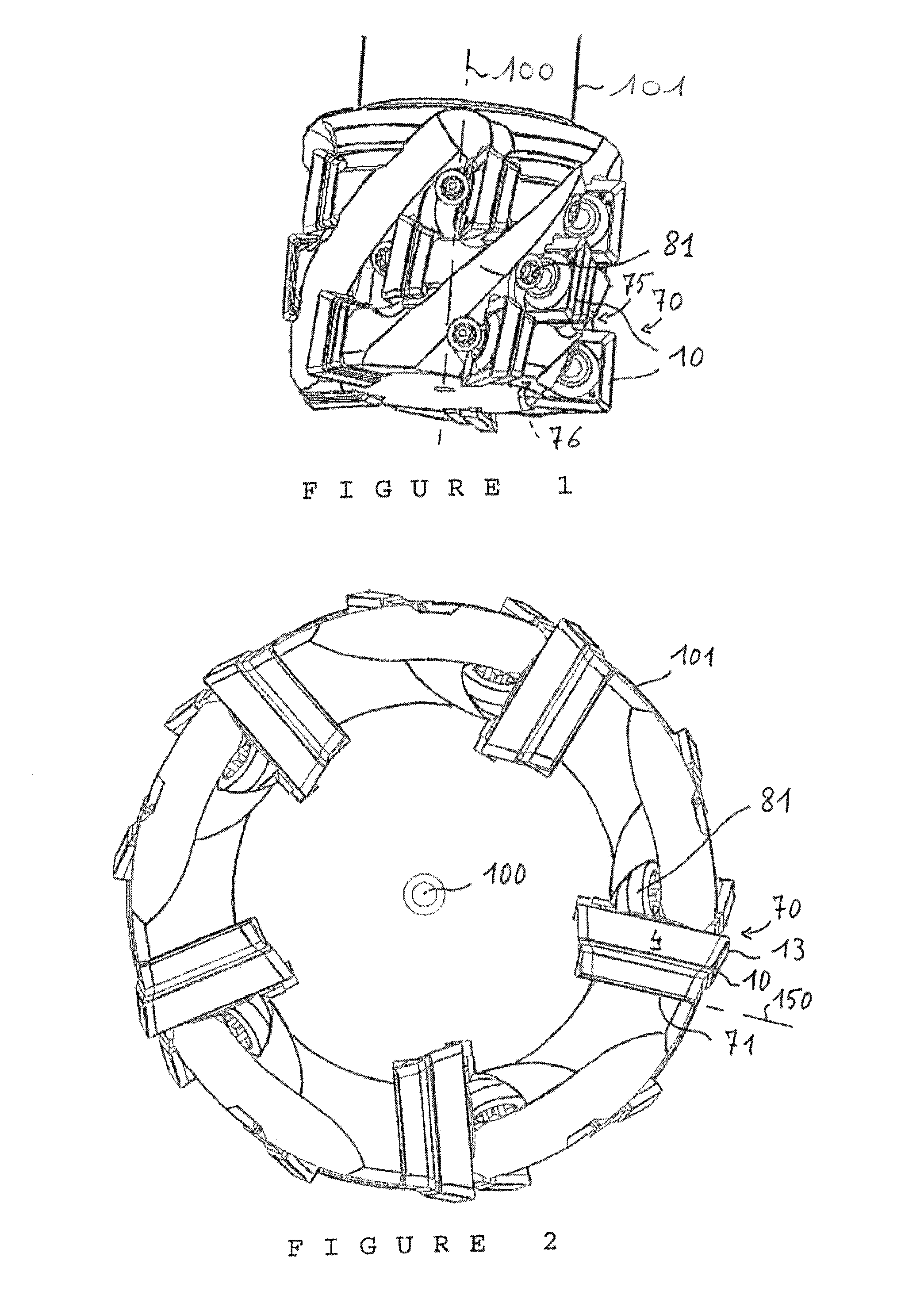
[0045]FIGS. 1 and 2 show a tool holder which is in the form of a rotary cutter 101, with rotation symmetry about a central axis 100, and including at a front end (FIG. 2) thereof, a head formed by a plurality of, here, five identical pockets, all referenced 70, distributed equi-angularly. Each pocket 70 comprises a slot-like seat extending in a generally axial plane separated by 72° from an adjacent pocket 70. The pocket 70 has a horizontal bottom 71, or base, which is here called “horizontal” because it extends in a plane 150 having a substantially radial direction of extension relative to the rotational axis 100.

[0046]With reference to FIGS. 4 to 8, a head 82, of a driving and final clamping screw 81 includes an end operating section of circular cross-section 83, here with a cylindrical envelope surface, which continues to a tapered neck portion 84 connecting to a threaded body 85 having an axis 80 (FIG. 4). Threaded body 85 is engaged with a threaded hole 91 formed in the cutter ...


PUM

PropertyMeasurementUnit
Forceaaaaaaaaaa
Lengthaaaaaaaaaa
Volumeaaaaaaaaaa

Abstract

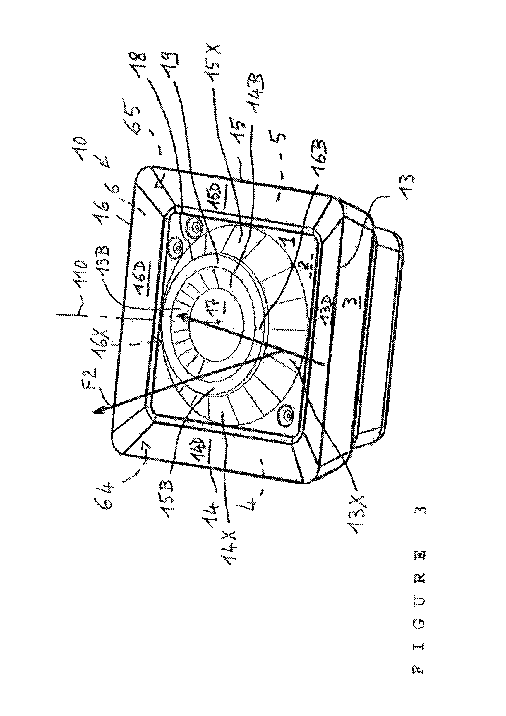
A tool holder having a cutting insert comprising an upper face having a pair of protruding surfaces, i.e. an abutment surface for clamping of the insert by means of a screw in a tool holder, and a deflection surface for deflecting chips away from the screw.

Description

CROSS REFERENCE TO RELATED APPLICATIONS[0001]This application is a national phase filing of International Application No. PCT / IB2009 / 000479 filed on Mar. 10, 2009 titled “CUTTING INSERT HAVING A CHIP DEFLECTOR”, which claims priority of French Patent Application No. 0801285 filed on Mar. 10, 2008. The contents of the above-identified Applications are relied upon and incorporated herein by reference in their entirety.BACKGROUND OF THE INVENTION[0002]The present invention relates to cutting inserts.[0003]A cutting insert must be precisely positioned on a tool holder in order to accurately machine a workpiece and also to avoid setting up stresses that may damage the cutting insert and the associated clamping member.[0004]There are several types of devices for clamping the insert in a pocket of the tool holder. In general, the principle of each type of device sets out to facilitate the operation of setting up and removing the cutting insert, while seeking to safeguard against any improp...

Claims


Application Information

Patent Timeline
IPC IPC(8): B23C5/22B23C5/28
CPCB23C2210/165Y10T407/2284B23C5/2243B23C5/109B23B2240/24Y10T407/23B23C2250/12B23C2200/085Y10T407/24Y10T407/191B23C2200/083Y10T407/2268B23C2200/086Y10T407/14
Inventor FOUQUER, RICHARD
Owner SAFETY SA
Learn More