
Method of making an electrically-heated hose assembly

a technology of electrical heating and hoses, applied in the direction of pipe heating/cooling, manufacturing tools, machines/engines, etc., can solve the problems of relative high freezing point of urea solution and rendering the scr system non-operational

Active Publication Date: 2014-09-02
PARKER INTANGIBLES LLC
View PDF14 Cites 2 Cited by
  • Summary
  • Abstract
  • Description
  • Claims
  • Application Information

AI Technical Summary

Benefits of technology

The present invention provides the ability to heat conventional push-in fitting types, like SAE J2044, without the need for specially-designed heated fittings. By varying the length of the wires recovered and the length of the hose from which the final length is cut, the amount of heat input to the fitting can be controlled without having to provide separate heated fittings of different wattages. These technical effects provide cost savings and improved efficiency for heating wires in push-in fittings.

Problems solved by technology

A common problem of urea-based SCR systems is the relatively high freezing point of the urea solution.
When freezing occurs, the SCR system is rendered non-operational because the urea catalyst solidifies and cannot be pumped through the hose assemblies into the exhaust stream.

Method used


Image

  • Method of making an electrically-heated hose assembly
  • Method of making an electrically-heated hose assembly
  • Method of making an electrically-heated hose assembly

Examples


Embodiment Construction

[0018]Certain terminology may be employed in the following description for convenience rather than for any limiting purpose. For example, the terms “forward” and “rearward,”“front” and “rear,”“right” and “left,”“upper” and “lower,” and “top” and “bottom” designate directions in the drawings to which reference is made, with the terms “inward,”“inner,”“interior,” or “inboard” and “outward,”“outer,”“exterior,” or “outboard” referring, respectively, to directions toward and away from the center of the referenced element, the terms “radial” or “horizontal” and “axial” or “vertical” referring, respectively, to directions or planes which are perpendicular, in the case of radial or horizontal, or parallel, in the case of axial or vertical, to the longitudinal central axis of the referenced element, and the terms “downstream” and “upstream” referring, respectively, to directions in and opposite that of fluid flow. Terminology of similar import other than the words specifically mentioned abov...


PUM

PropertyMeasurementUnit
freezing temperatureaaaaaaaaaa
temperaturesaaaaaaaaaa
lengthaaaaaaaaaa

Abstract

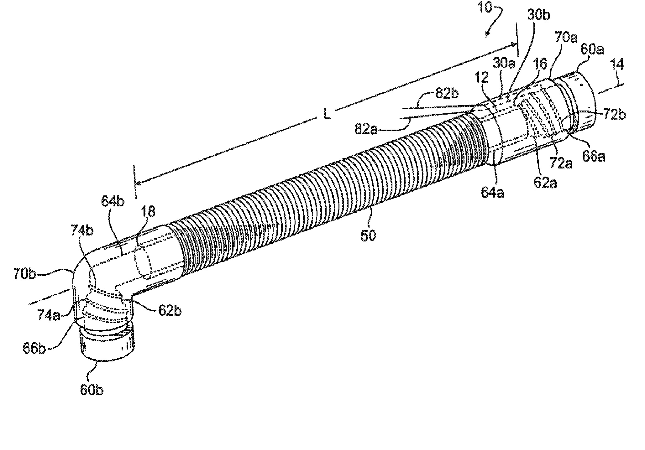
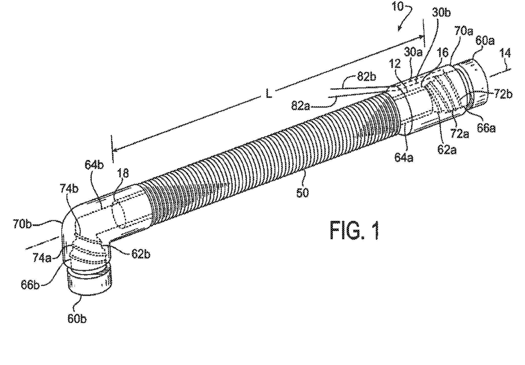
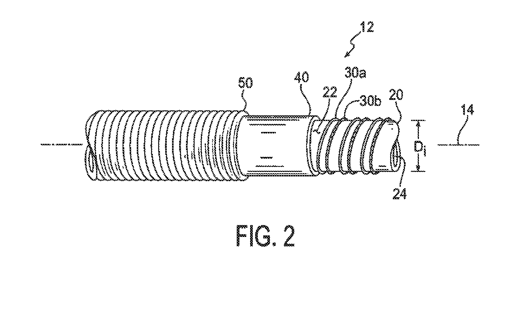
Electrically-heated hose assembly including a hose and a first and a second fitting. The hose is constructed as having a core tube, a pair of spiral wound wires surrounding the core, and a jacket surrounding the core tube. A first end of each of the fittings is within a corresponding end of the hose, with a second end of the fittings extending beyond the hose end. The wires are wound around at least a portion of the second fitting end of a corresponding one of the fittings.

Description

BACKGROUND OF THE INVENTION[0001]The present invention relates broadly to an electrically-heated hose assembly, and more particularly to such an assembly for use in transferring a urea, i.e., carbamide, solution in a diesel engine emissions after-treatment system.[0002]Selective catalytic reduction (SCR) is a method of converting nitrogen oxides (NOx) into diatomic nitrogen (N2O) and water with the aid of an emission reduction reagent such as urea. SCR is used to reduce emissions in diesel engines such as for ships, locomotives, gas turbines, and trucks.[0003]SCR systems inject a liquid urea solution or other catalyst into a stream or flue of exhaust gas. The exhaust gas is absorbed into the urea solution whereupon the nitrogen oxides (NOx) in the gas are converted into diatomic nitrogen by means of a chemical reaction[0004]The basic components of a urea-based SCR system, such as may be used on a heavy duty truck for example, are a urea solution tank, pressure regulators, a control ...

Claims


Application Information

Patent Timeline
Patent Type & Authority Patents(United States)
IPC IPC(8): H05B3/58F16L53/00H05B3/00F16L25/01F01N3/20F16L53/38
CPCF01N3/2066F01N2610/02F16L53/008F01N2610/14H05B3/58F01N2610/10F16L25/01Y10T29/49826Y10T29/49083Y10T29/49087F16L53/38Y02T10/12
Inventor POWELL, STEVEN M.SILBER, MARK G.HENRY, TY A.EDWARDS, GERALD F.JOHNSTON, JAMES L.LININGER, THOMAS B.PETER, MATTHEW R.FISHER, WILLIAM C.MARTINO, NICK A.
Owner PARKER INTANGIBLES LLC
Learn More