
Hydrodynamic torque converter with torsion vibration damper

a technology of torsion vibration and hydrodynamic torque converter, which is applied in the direction of rotary clutches, fluid couplings, gearings, etc., can solve the problems of complex, expensive, and complex fabrication of hydrodynamic torque converters, and achieve the effect of improving the hydrodynamic torque converter

Inactive Publication Date: 2014-08-26
SCHAEFFLER TECH AG & CO KG
View PDF15 Cites 3 Cited by
  • Summary
  • Abstract
  • Description
  • Claims
  • Application Information

AI Technical Summary

Benefits of technology

The invention is about improving a hydrodynamic torque converter with a torsion vibration damper to avoid complex configurations and costly modifications. The solution involves using a simple disc-shaped component that can be easily fabricated at a low cost and without significant fabrication complexity. The centering devices on the disc-shaped component and the axial bearing are configured in a limited local manner to enable easy movement and arrangement. This allows for efficient use of the installation space and minimizes the required modifications to the elements. The centering devices can be configured between the same disc-shaped component and the axial bearing, which simplifies the production process of the second component. The solution also includes options for a complementary arrangement of centering units at the disc-shaped component and the axial bearing, which helps to minimize the manufacturing complexity and facilitates the use of standardized elements. Overall, the invention simplifies the manufacturing process, reduces costs, and allows for efficient use of installation space.

Problems solved by technology

For this purpose, a radial support surface has to be provided at the turbine hub, which makes fabrication more complex in particular when the turbine hub is configured as aluminum pressure cast component.
Thus, the element of the freewheeling clutch has to be modified with respect to this function, which necessitates special embodiments of these elements, which are very complex and expensive.

Method used


Image

  • Hydrodynamic torque converter with torsion vibration damper
  • Hydrodynamic torque converter with torsion vibration damper
  • Hydrodynamic torque converter with torsion vibration damper

Examples


first embodiment

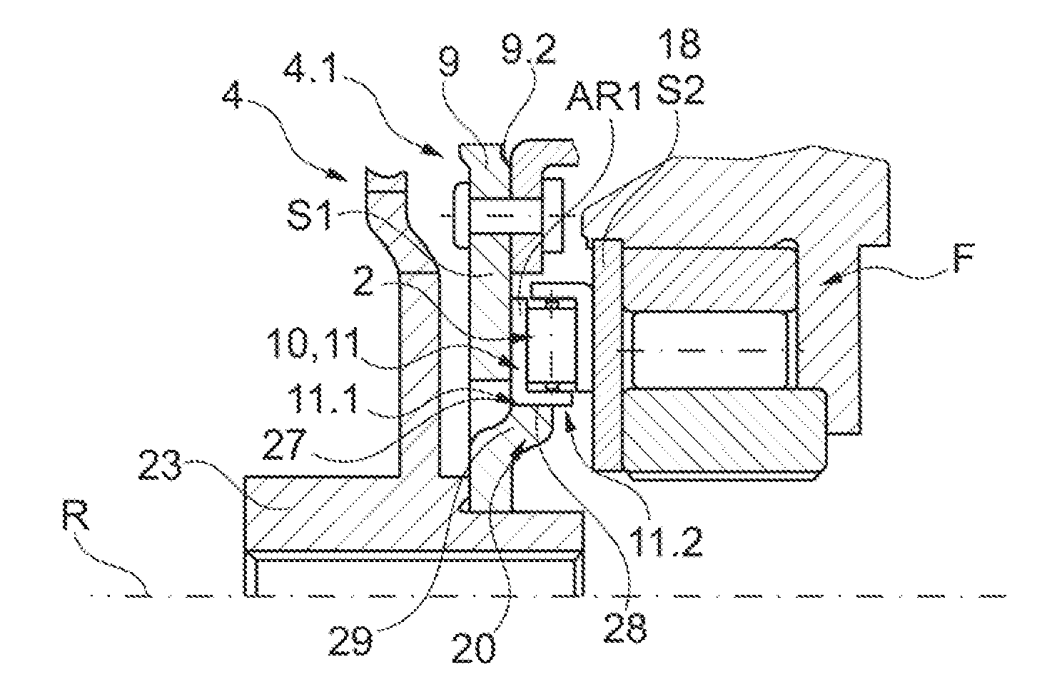
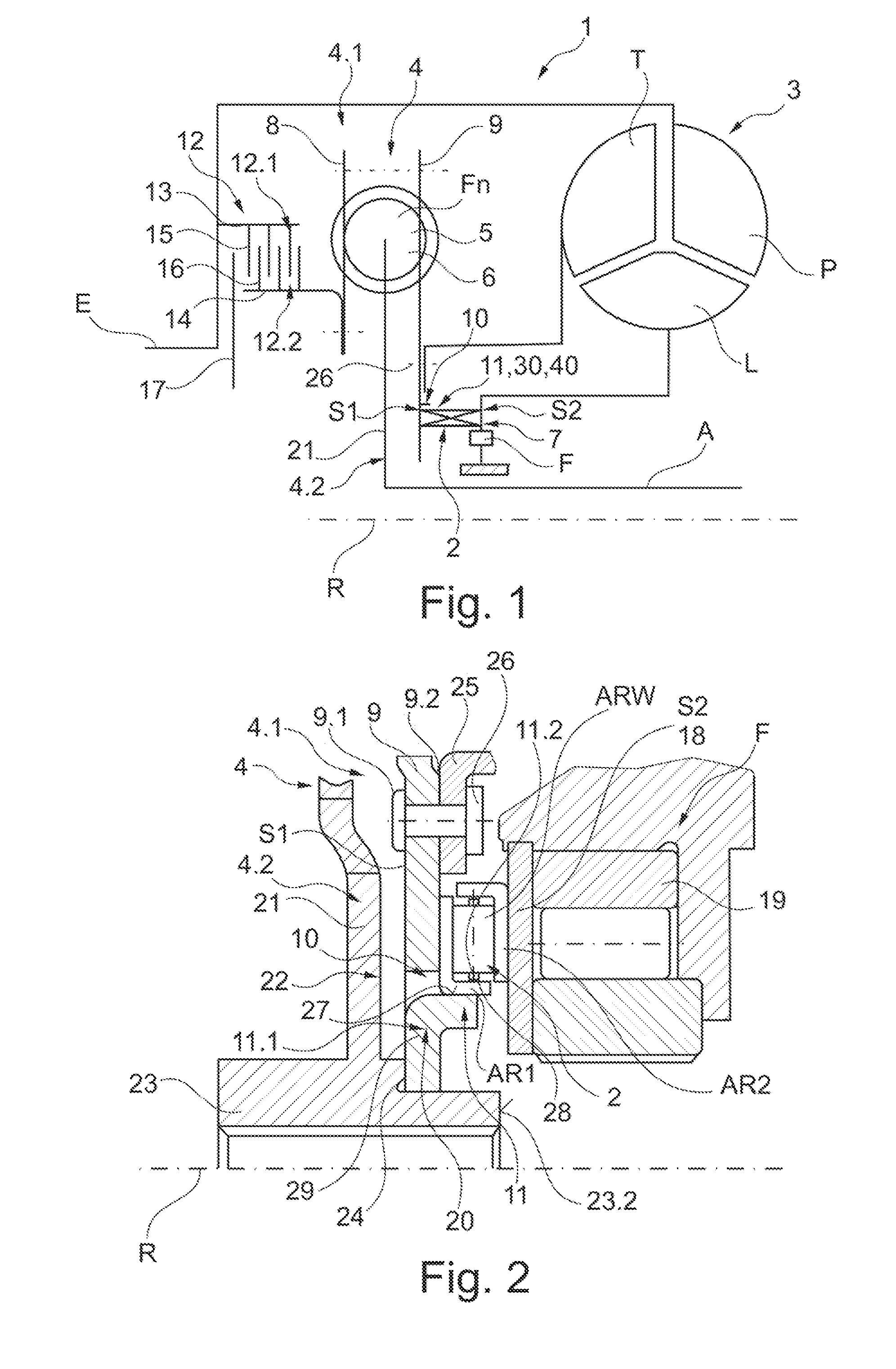
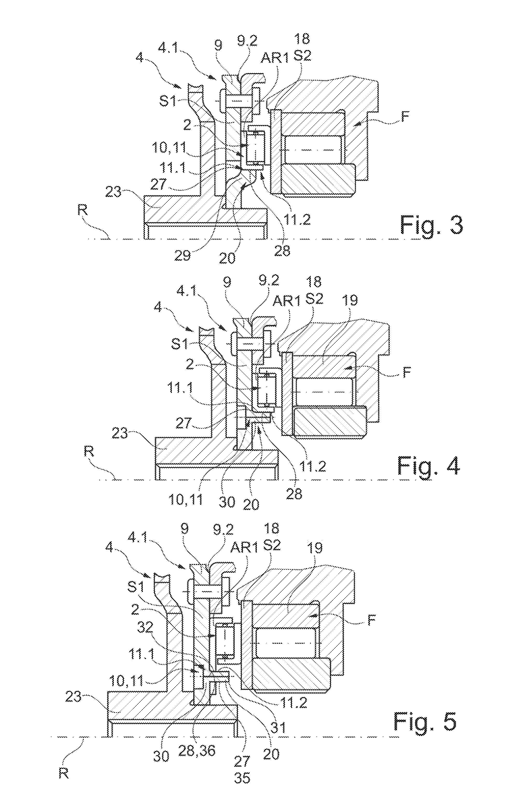
[0081]FIGS. 7 and 8 illustrate further variants of the configuration of the centering devices 11 according to the invention. They simultaneously form torque proof connections 39 between a disc shaped component, thus S1, and the axial bearing 2, in particular the axial bearing race AR1. Thus, the axial rises can be formed at one of the components, the disc shaped component S1 or the axial bearing 2 through integral or separate mounting elements which form the connection 39 with the centering unit at the other component.

[0082]FIG. 7 illustrates an embodiment of the centering units 11.1 and 11.2 forming a connection 39, in particular a non-disengageable connection by riveting together with integral configuration of the attachment elements at the disc shaped component S1 configured as an axial material draw-out 20. The axial material draw-out 20 simultaneously forms a rivet element 40 in the form of a pass-through rivet which is configured passing through the recess 32 at the axial bea...

second embodiment

[0087]FIG. 9 through 11 illustrate possible variants of the centering according to the invention through engagement. The devices 10 include devices 34 for engaging the axial bearing 2 in at least one of the adjacent disc shaped components S1 and / or S2. They include radial support surfaces 27 at one of the disc shaped components S1 or S2 configured circumferential at least in circumferential direction, or several of them disposed offset in circumferential direction, and complementary radial surfaces 28 or a circumferential surface 28 at the axial bearing 2 interacting with disc shaped components S1 or S2. Thus, a rise extending in axial direction is provided at the axial bearing 2, in particular a protrusion 38 which forms the radially oriented surface or surfaces 28.

[0088]FIG. 9 illustrates a first particularly advantageous embodiment which does not require any modification at the disc shaped component S1. The axial bearing race AR1 is formed, so that it is configured extending in ...

third embodiment

[0090]FIGS. 11 through 13 illustrate variants of the solution according to the invention through centering at one of the connecting components. Also here the cut out from the torque transmission device 1 is illustrated again as depicted in FIG. 1.

[0091]The devices 10 in FIG. 11 include a centering in a radial direction in the portion of the outer circumference of the axial bearing 2 or outside through an extension of one of the axial bearing rings, thus of the axial bearing ring AR1 in radial direction in the portion outside of the axial bearing 2. The centering is performed in FIG. 11 at the turbine shell disc 25 or at an element connected torque proof therewith in particular ears 42 formed at the turbine shell disc in radial direction. By comparison FIG. 12 illustrates a centering in a portion of the inner circumference or within the inner circumference of the axial bearing 2 at a connecting component, in particular at the damper hub 23. For axial securing a securing element can b...


PUM


Abstract

The invention relates to a hydrodynamic torque converter, comprising: a torsion vibration damper and an axial bearing disposed between a damper component of the torsion vibration damper or a turbine shell of the hydrodynamic torque converter, the turbine shell connected with the damper component, and an adjacent connecting component; and devices for centering the axial bearing in a radial direction. The invention is characterized in that the axial bearing is disposed between two disc shaped components and the centering devices are disposed at least at one of the two disc shaped components.

Description

CROSS REFERENCE TO RELATED APPLICATIONS[0001]This application is filed under 35 U.S.C. §120 and §365(c) as a continuation of International Patent Application PCT / DE2010 / 001230 filed Oct. 18, 2010, which application claims priority from German Patent Application No. 10 2009 052 295.6 filed Nov. 9, 2009 and from German Patent Application No. 10 2010 027 255.8 filed Jul. 15, 2010, which applications are incorporated herein by reference.FIELD OF THE INVENTION[0002]The invention relates to a hydrodynamic torque converter with a torsion vibration damper and an axial bearing disposed between a damper component of the torsion vibration damper or a turbine shell of the hydrodynamic torque converter connected to the torsion vibration damper, and an adjacent connecting component, and the invention also relates to devices for centering the axial bearing in radial direction.[0003]The invention relates in particular to a hydrodynamic torque converter configured for application in automated straig...

Claims


Application Information

Patent Timeline
Patent Type & Authority Patents(United States)
IPC IPC(8): F16H45/02F16H41/24
CPCF16H45/02F16H41/24F16H2041/246F16H2045/021
Inventor MAIENSCHEIN, STEPHAN
Owner SCHAEFFLER TECH AG & CO KG
Learn More