
Distance measuring apparatus and distance measuring method

a distance measurement and distance measurement technology, applied in the field of distance measuring apparatus and distance measuring method, can solve the problem of restricting the design of the arrangement of pixels in the image pickup element, and achieve the effect of relaxing the restrictions on the arrangement of pixels and improving the flexibility of design

Active Publication Date: 2020-05-26
CANON KK
View PDF6 Cites 0 Cited by
  • Summary
  • Abstract
  • Description
  • Claims
  • Application Information

AI Technical Summary

Benefits of technology

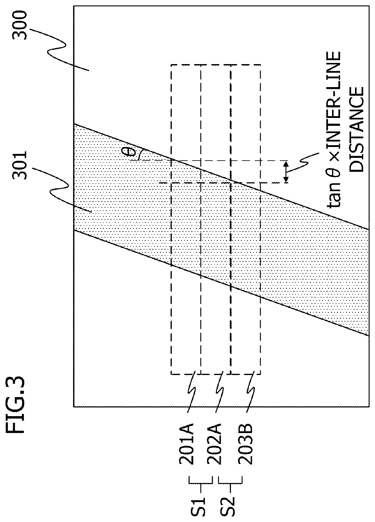
[0006]With the foregoing in view, it is an object of the present invention to provide a technique in which, while maintaining the equivalent effect, to that of the prior art, of correcting the displacement amount included in the correlation values, generated when the comparing regions of the images of an object are different, restrictions on the pixel arrangement can be relaxed, and in which design flexibility can be improved.
[0024]According to the present invention, while maintaining the equivalent effect, to that of the prior art, of correcting the displacement amount included in the correlation values, generated when the comparing regions of the images of an object are different, restrictions on the pixel arrangement can be relaxed, and design flexibility can be improved.

Problems solved by technology

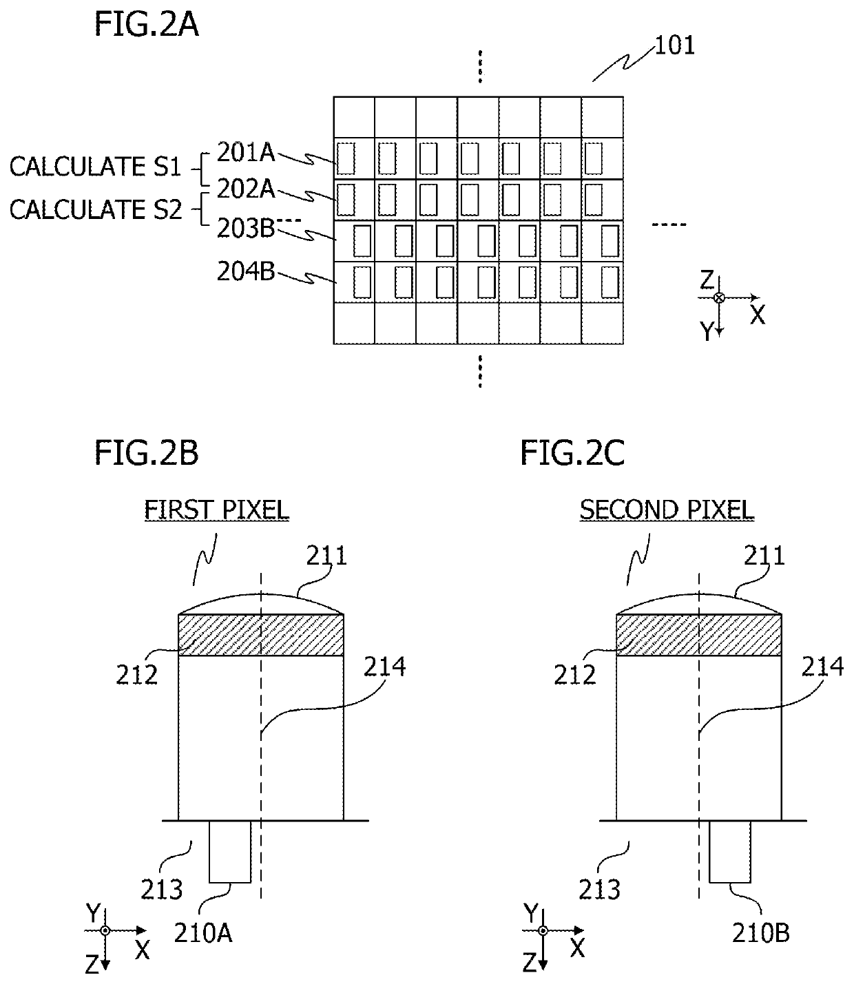
Furthermore, the pixels in the above and below reading lines need to have the same aperture profiles, which restrict designing to arrange pixels in the image pickup element.

Method used


Image

  • Distance measuring apparatus and distance measuring method
  • Distance measuring apparatus and distance measuring method
  • Distance measuring apparatus and distance measuring method

Examples


first embodiment

[0039]First embodiment of the present invention will be described.

[0040]

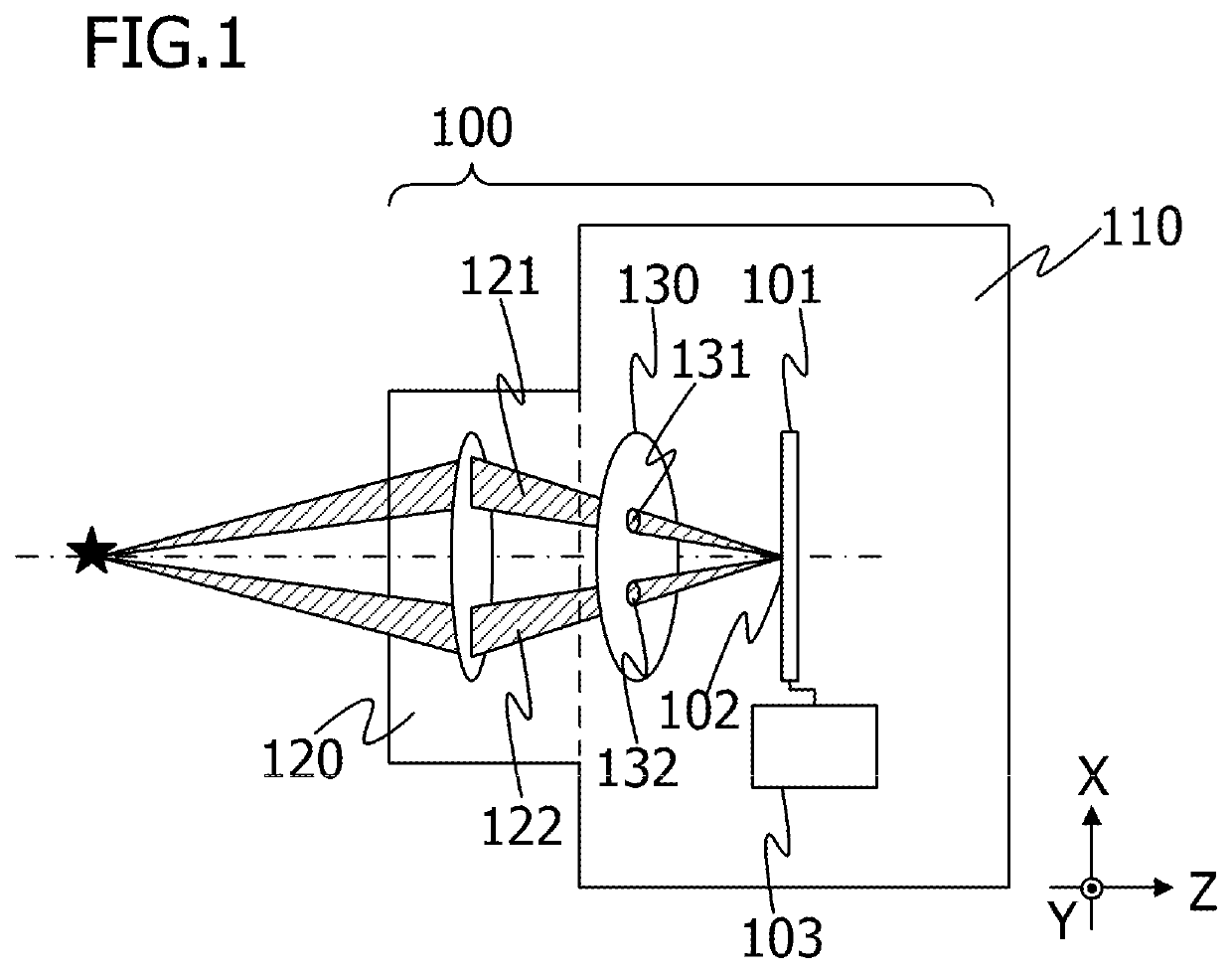
[0041]FIG. 1 is a diagram depicting a configuration example of a distance measuring apparatus 100 according to First embodiment. The distance measuring apparatus 100 according to First embodiment includes a camera 110 and an imaging optical system 120. The camera 110 includes an image pickup element 101, an arithmetic processing unit 103 (acquiring unit) and the like. In the image pickup element 101, a plurality of pixels 102, which receive the light of the image formed by the imaging optical system 120, are two-dimensionally arrayed. Each pixel 102 is configured to have a light-receiving sensitivity characteristics in accordance with an incident angle of the light, so as to acquire a parallax image.

[0042]The arithmetic processing unit 103 may be constituted by a logic circuit, such as an application specific integrated circuit (ASIC). Alternatively, the arithmetic processing unit 103 may be constituted by a cen...

second embodiment

[0092]In Second embodiment, a case when pixels to acquire an image for viewing (full aperture pixels) exist in the image pickup element will be described.

[0093]FIG. 8A indicates an image pickup element 601 according to Second embodiment. The image pickup element 601 in FIG. 8A includes a first pixel line 603A where first pixels are arranged, a second pixel line 604B where second pixels are arranged, and third pixel lines 601C, 602C, 605C and 606C where third pixels, which are pixels to acquire an image for viewing, are arranged. In the other regions of the image pickup element 601, a set of four lines (third pixels lines 601C, 602C, first pixel line 603A, and second pixel line 604B) is repeatedly disposed.

[0094]FIG. 8B is a diagram depicting a configuration of the third pixel. The third pixel includes a micro-lens 611 and a color filter 612, and forms a photoelectric converting unit 610C on a substrate 613. The photoelectric converting unit 610C generates an output signal by receivi...

third embodiment

[0099]In Third embodiment, an example of correcting the displacement amount caused by the line displacement in the comparing regions in a stereo camera will be described. In Third embodiment, two cameras are used as a distance measuring apparatus. Each camera has an image pickup element in which pixels, to acquire an image for viewing (full aperture pixels), are disposed. The distance measuring apparatus acquires the distance information based on the image signals having parallax which are outputted from the cameras respectively.

[0100]FIG. 9 is a diagram depicting a configuration of a distance measuring apparatus according to Third embodiment. The distance measuring apparatus according to Third embodiment includes two cameras 711 and 712, an arithmetic processing unit 703 (acquiring unit or arithmetic processing apparatus) that calculates the image displacement amount by processing the output signals from the cameras, among other components. The camera 711 includes a lens 721 which ...


PUM


Abstract

A distance measuring apparatus includes: an image pickup element in which a plurality of pixels receives light of an image are two-dimensionally arrayed; and an acquiring unit acquires information relating to a distance to an object based on an output signal of the image pickup element which each pixel line is constituted by pixels which receive beams passing through a same pupil region of the imaging optical system, and wherein the acquiring unit (1) acquires a first image displacement amount from output signals of at least two pixel lines which receive beams passing through a same pupil region, (2) acquires a second image displacement amount from output signals of at least two pixel lines which receive beams passing through different pupil regions, and (3) acquires the information relating to the distance to the object based on the first image displacement amount and the second image displacement amount.

Description

BACKGROUND OF THE INVENTIONField of the Invention[0001]The present invention relates to a distance measuring apparatus and a distance measuring method.Description of the Related Art[0002]As a distance method used for a digital single-lens reflex camera and the like, a method of calculating information relating to the distance to an object, using a parallax amount determined from correlation values among a plurality of images having parallax, is frequently used (phase difference distance measuring method). In concrete terms, the parallax amount is measured as a displacement amount among a plurality of images with respect to the pixel coordinates, and this displacement amount is also called the “image displacement amount”.[0003]A correlation value is determined by extracting a part of each image as a comparing region, and performing the correlation operation. Here if the comparing regions among the images are different portions of the object, a value other than the parallax amount to ...

Claims


Application Information

Patent Timeline
Patent Type & Authority Patents(United States)
IPC IPC(8): G06T7/593H04N13/239H04N13/00G06T7/73G06T7/32H04N13/232H04N13/218
CPCG06T7/32G06T7/74H04N13/218H04N13/232G06T7/593G06T2207/20216H04N2013/0081H04N13/239G06T2207/20224G06T2207/10012
Inventor OIGAWA, MAKOTO
Owner CANON KK
Learn More