
Separator for fuel cell, fuel cell and method of manufacturing fuel cell

a technology of separator and fuel cell, which is applied in the direction of fuel cell details, electrochemical generators, final product manufacture, etc., can solve the problems of less flexibility in arrangement of flow paths for fluids, less flexibility in thermal design in cell plane, and less flexibility in arrangement. , to achieve the effect of improving the flexibility in setting the flow direction, less flexibility in arrangement, and less flexibility in thermal design

Inactive Publication Date: 2019-07-02
TOYOTA JIDOSHA KK
View PDF48 Cites 0 Cited by
  • Summary
  • Abstract
  • Description
  • Claims
  • Application Information

AI Technical Summary

Benefits of technology

Enables flexible fluid flow path arrangements, improves thermal design, reduces weight and cost, and enhances the durability and efficiency of fuel cell performance by preventing stagnation and pressure loss.

Problems solved by technology

In the separator of the known corrugated structure described above, however, the flow direction in the flow path for one fluid formed on one surface and the flow direction in the flow path for another fluid formed on the other surface are limited to the mutually parallel directions.
There is accordingly the less flexibility in arrangement of the flow paths for the fluids.
The fuel cell using this separator accordingly has the limitation in arrangement of the respective manifolds and the less flexibility in thermal design in the cell plane.
The increase in total number of parts, however, undesirably leads to weight expansion, size expansion and cost increase.
This arrangement further reduces the non-uniformity of the temperature distribution of the fuel cell, thereby preventing the resulting local dry-up or local flooding and minimizing the deterioration of the durability of the electrolyte membrane.

Method used


Image

  • Separator for fuel cell, fuel cell and method of manufacturing fuel cell
  • Separator for fuel cell, fuel cell and method of manufacturing fuel cell
  • Separator for fuel cell, fuel cell and method of manufacturing fuel cell

Examples


first embodiment

A. First Embodiment

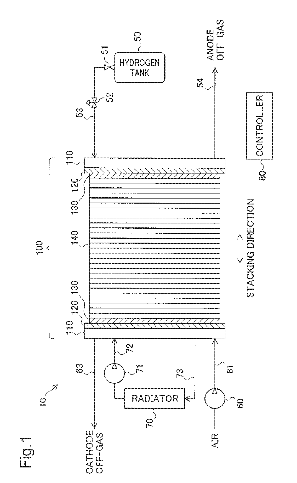
[0107]FIG. 1 is an explanatory diagram illustrating the schematic configuration of a fuel cell system 10 according to a first embodiment of the invention. The fuel cell system 10 includes a fuel cell 100. The fuel cell 100 has a stack structure formed by stacking an end plate 110, an insulator plate 120, a collector plate 130, a plurality of unit cells 140, a collector plate 130, an insulator plate 120 and an end plate 110 in this sequence.

[0108]Hydrogen as a fuel gas is supplied from a hydrogen tank 50 for storing high-pressure hydrogen to the fuel cell 100 via a shut-off valve 51, a regulator 52, and a piping 53. The supplied hydrogen is distributed into the respective unit cells 140 via a fuel gas supply manifold (described later) and is used for power generation by the respective unit cells 140. The hydrogen that is not used by the respective unit cells 140 (anode off-gas) is collected via a fuel gas exhaust manifold (described later) and is discharged through...

second embodiment

B. Second Embodiment

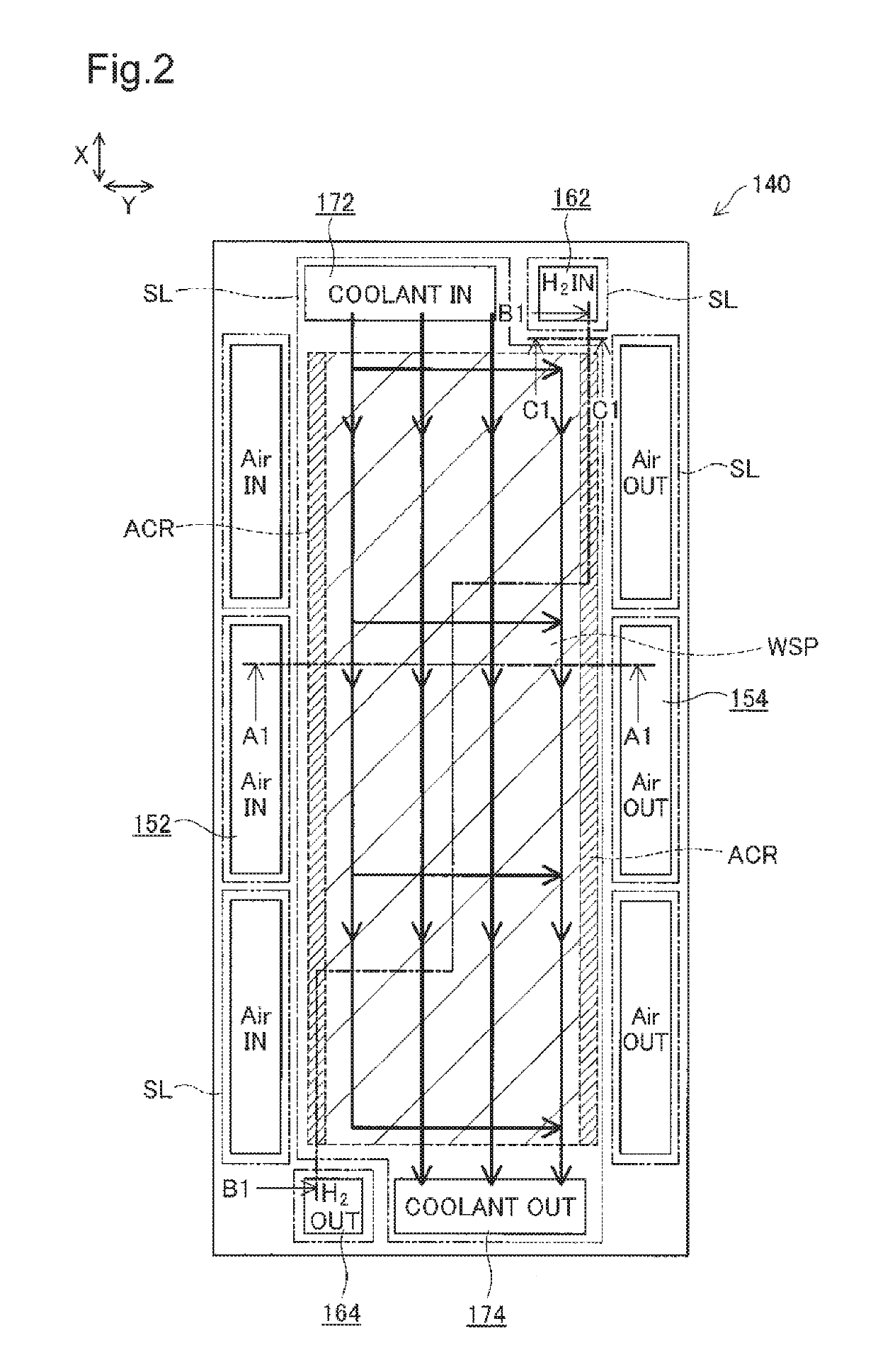
[0137]FIG. 7 is an explanatory diagram illustrating the cross sectional structure of a fuel cell 100 according to a second embodiment. FIG. 7 shows a partial cross section of the fuel cell 100 at the position of B1-B1 in FIG. 2. The fuel cell 100 of the seventh embodiment differs in the arrangement of tunnel flow paths TR from the fuel cell 100 of the first embodiment (FIG. 4), but otherwise has the similar structure to that of the fuel cell 100 of the first embodiment. The tunnel flow path TR is a flow path that runs below the seal lines SL formed by the seals 440 and 450 (on the side of the power generation layer 200). Like the first embodiment, the tunnel flow path TR of the second embodiment is provided as a flow path that communicates between the fuel gas supply manifold 162 and the common rail ACR for the fuel gas and between the fuel gas exhaust manifold 164 and the common rail ACR for the fuel gas.

[0138]In the fuel cell 100 of the first embodiment, the tu...

third embodiment

C. Third Embodiment

[0142]FIG. 8 is an explanatory diagram illustrating the structure around tunnel flow paths TR in a fuel cell 100 according to a third embodiment. FIG. 8 shows the plane of the tunnel flow paths TR and the common rail ACR for the fuel gas communicating with the tunnel flow paths TR and the cross sections at a position A2-A2 and at a position B2-B2 on the plane. The fuel cell 100 of the third embodiment differs in the arrangement of the tunnel flow paths TR from the fuel cell 100 of the first embodiment, but otherwise has the similar structure to that of the fuel cell 100 of the first embodiment. Each of the tunnel flow paths TR is provided as a flow path that runs below the seal lines SL formed by the seals 440 and 450 (on the side of the power generation layer 200) to communicate between the fuel gas supply manifold 162 and the common rail ACR for the fuel gas and between the fuel gas exhaust manifold 164 and the common rail ACR for the fuel gas.

[0143]As shown in ...


PUM

PropertyMeasurementUnit
pressure lossaaaaaaaaaa
curvature radius Raaaaaaaaaaa

Abstract

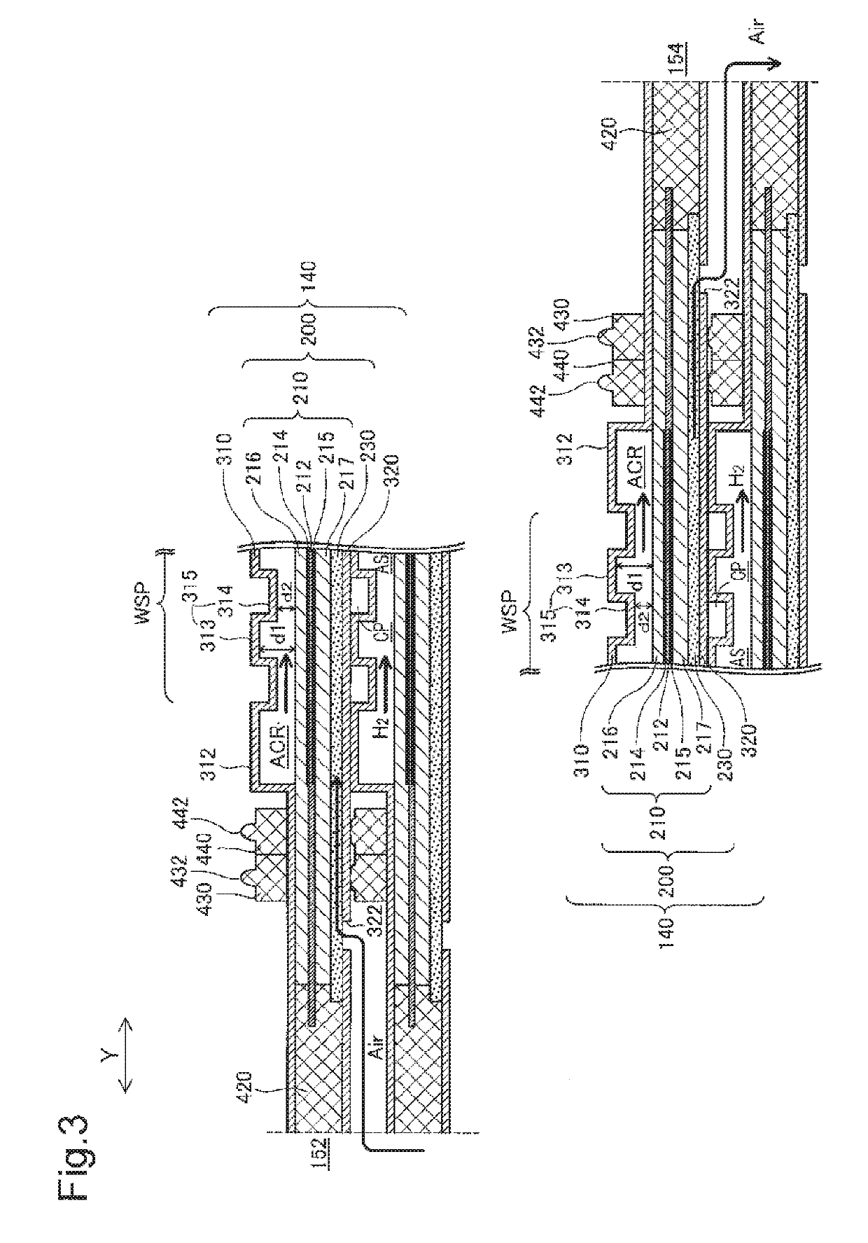
A separator for fuel cell includes a corrugated portion formed to have a corrugated cross section where a first groove that is concave to a first surface to form a flow path for a first fluid on the first surface and a second groove that is concave to a second surface opposite to the first surface to form a flow path for a second fluid on the second surface are arranged alternately and repeatedly. Each of the second grooves has at least one shallower groove section formed to have a less depth from the second surface than depth of a remaining groove section and provided to form a communication flow channel on the first surface side, which is arranged to communicate between two flow path spaces for the first fluid that are adjacent to each other across the shallower groove section.

Description

CROSS REFERENCE TO RELATED APPLICATIONS[0001]This is a continuation of U.S. patent application Ser. No. 13 / 822,995, filed Mar. 13, 2013, which is the National Stage of International Application No. PCT / JP2010 / 005666, filed Sep. 16, 2010. The entire disclosures of the prior applications are considered part of the disclosure of the accompanying continuation application, and are hereby incorporated by reference.TECHNICAL FIELD[0002]The present invention relates to a separator for fuel cell, a fuel cell, and a method of manufacturing a fuel cell.BACKGROUND ART[0003]A fuel cell, for example, a polymer electrolyte fuel cell, is generally used in a stacked structure where a plurality of power generation layers, each including an electrolyte membrane and a pair of electrodes (anode and cathode), are stacked via separators for separating a fuel gas and an oxidizing gas used as reactive gases from each other. Flow paths that allow fluids, such as the reactive gases and a cooling medium (e.g.,...

Claims


Application Information

Patent Timeline
Patent Type & Authority Patents(United States)
IPC IPC(8): H01M8/0265H01M8/0267H01M8/241H01M8/0276H01M8/1018H01M8/0271H01M8/0258H01M8/0254H01M8/026H01M8/0286
CPCH01M8/0265H01M8/026H01M8/0254H01M8/0258H01M8/0267H01M8/0276H01M8/1018H01M8/241H01M8/0271Y02P70/56H01M8/0286H01M2008/1095H01M8/2432H01M8/2483Y02E60/50Y02P70/50
Inventor OKABE, HIROKINAKAJI, HIROYAYOSHIDA, MAKOTOHAMADA, SHIGETAKAKURIHARA, TAKUYASATO, KENJITANAKA, HIDEAKINAKAGAKI, NOBUHIKOUEDA, JUNJIKINOSHITA, KATSUHIKO
Owner TOYOTA JIDOSHA KK
Learn More