
Encapsulated polymer network liquid crystal material, device and applications

a polymer network and liquid crystal material technology, applied in liquid crystal compositions, instruments, chemistry apparatuses and processes, etc., can solve the problems of reducing the probability of damage to the panel under test, and achieve the effects of improving electro-optical performance, improving mechanical properties such as rigidity and hardness, and simplifying the manufacturing process

Active Publication Date: 2014-08-12
ORBOTECH LTD
View PDF79 Cites 5 Cited by
  • Summary
  • Abstract
  • Description
  • Claims
  • Application Information

AI Technical Summary

Benefits of technology

[0013]Embodiments of the present invention provide improved polymer network liquid crystal sensor materials having improved mechanical properties such as rigidity and hardness and the PNLC substantially improves electro-optical performance. The PNLC sensor materials can be manufactured with an emulsion process so as to simplify substantially the manufacturing process. The emulsion process can create a plurality of droplets of liquid crystal material having an appropriate distribution of sizes that can be within a range from about 1 um to about 10 um. The water based encapsulation process can be combined with UV curing so as to form the polymer network within plurality of droplets of the liquid crystal. In many embodiments, each LC droplet is configured with the polymer network extending substantially across the LC droplet, and the polymer network may contact the interfacial material or the polymer matrix at the outer boundary of the droplet without substantial anchoring of the polymer network. The polymer network of each of the plurality of liquid crystal droplets may comprise a material to lower substantially the switching voltage, such as a fluorinated acrylate, or a silicone acrylate, that may interact with the liquid crystal so as to lower the surface tension of the LC droplet. The encapsulated PNLC sensor material may comprise an interfacial layer combined with the polymer network so as to decrease substantially the driving voltage.
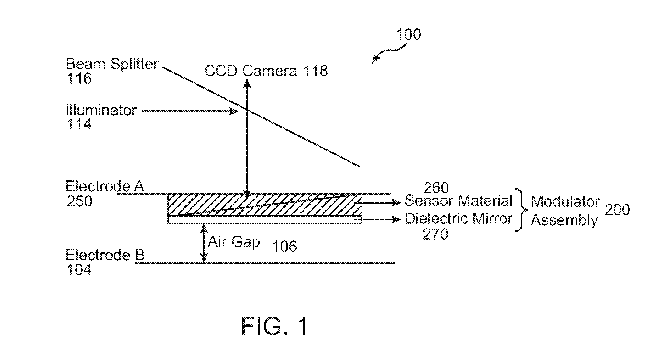
[0014]In many embodiments, a voltage imaging optical system comprises the electro-optical modulators made of the encapsulated PNLC material and has significantly improved defect detection and sensitivity without reduced mechanical properties such as reduced hardness. The modulators of the encapsulated PNLC material can also be operated at a much higher air gap with satisfactory defect detection sensitivity, so as to increase substantially the lifetime of the modulators when used with voltage imaging systems. In many embodiments, the encapsulated PNLC modulators can be operated with an air gap greater than 100 um above TFT panel, and an improvement in sensitivity to defects within a range from about 30% to about 70% can be achieved. The encapsulated PNLC modulators may have a substantially longer lifetime when operated at the higher air gap above TFT panel, as the probability of contact with the panels under test is reduced as well as the damage that may be related to particles or other residue on the panels. The probability of damage to the panel under test may also decrease.
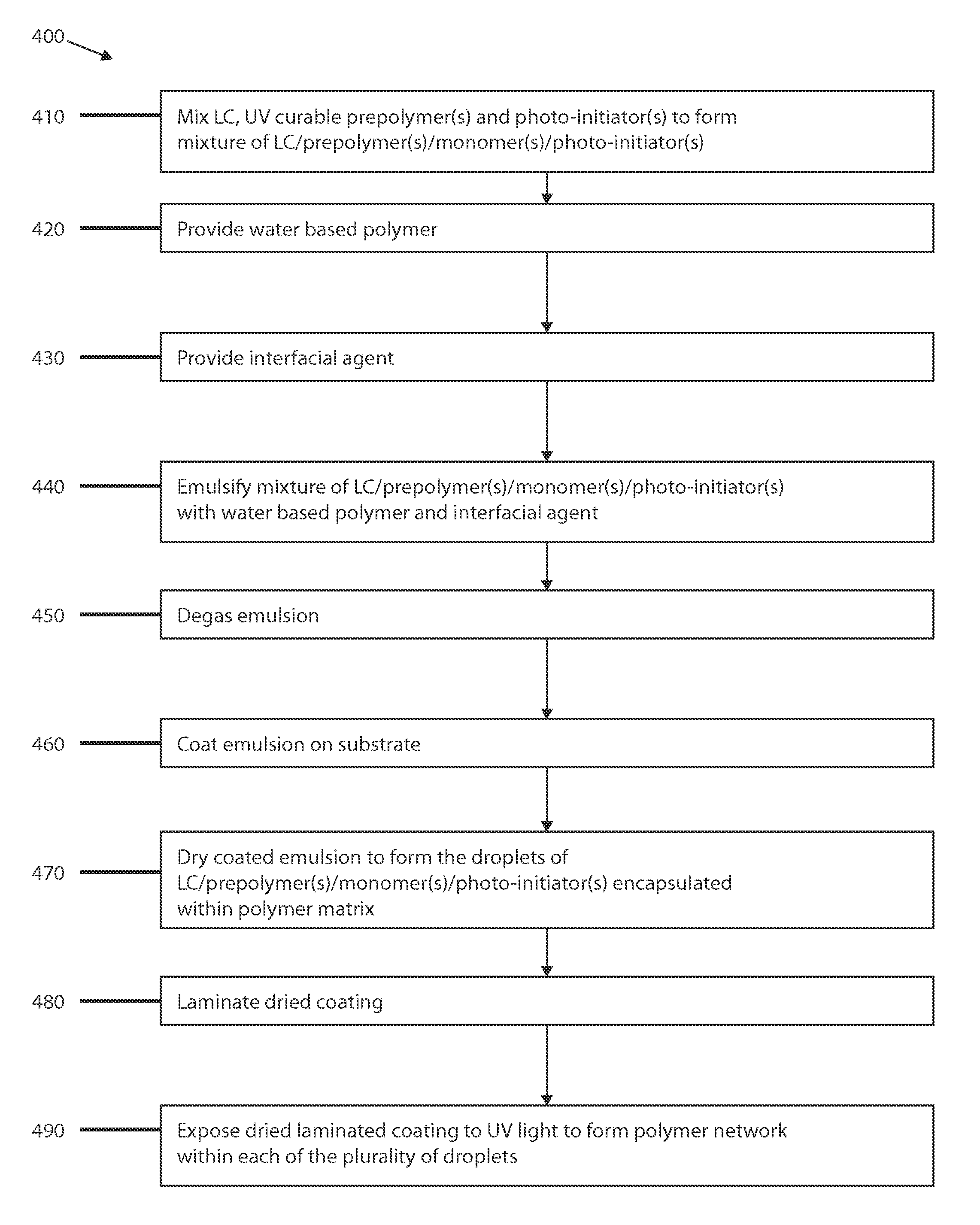
[0015]Many embodiments provide an improved method of manufacturing the encapsulated PNLC material. The improved emulsification process can be used for encapsulation of the LC droplets, such that the multiple components of the PNLC material can be combined. The components of the PNLC emulsion prior to drying can be distributed such that a majority of each of the monomers, the prepolymers, and the photo-initiators is dissolved in droplets of the liquid crystal, and the liquid crystal droplets can be substantially surrounded by an interfacial compound after the emulsification process. The components of the PNLC emulsion may form within the emulsion so as to provide a complex PNLC structure during the emulsification and coating process. The materials of the emulsion comprising the liquid crystal, the interface layer, and the polymer network can be combined so as to further reduce the switching voltage of the LC droplet within the polymer matrix.
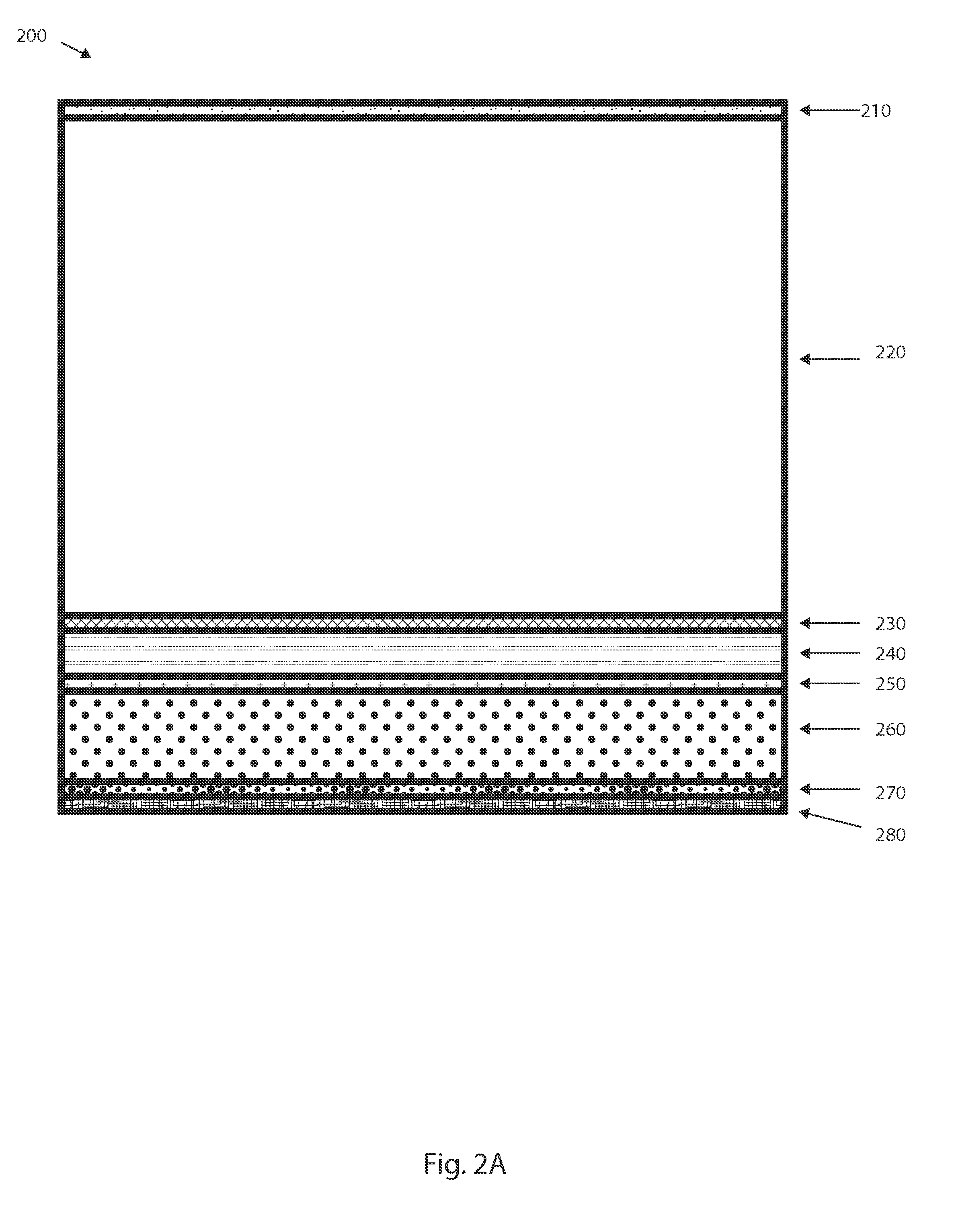
[0016]The PNLC material may comprise a plurality of components having structures configured so as to reduce substantially the switching voltage to transmit light. The PNLC material may comprise the plurality of droplets of the LC material so as to provide optical transmission in response to the driving voltage, the polymer network extending substantially across each of the droplets so to decrease the switching voltage, and the polymer matrix extending substantially around each droplet so as to provide mechanical rigidity and hardness. The PNLC sensor material may further comprise the interfacial layer so as to decrease the transmission voltage. The interfacial layer may encapsulate each droplet so as to reduce substantially the switching voltage, and the interfacial layer may comprise a double layer structure. The polymer matrix may comprise an amount of polymer sufficient so as to provide sufficient rigidity and hardness, for example with a weight ratio of polymer matrix to liquid crystal within a range from about 20 / 80 to about 50 / 50. The polymer matrix may comprise a polymer material such as polyurethane or polyacrylate latex, or mixtures thereof, so as to provide mechanical stability and film hardness. The polymer network may comprise one or more of many cross-linked materials, and may comprise a fluorinated component or a silicone acrylate component, or combinations thereof. The polymer network can provide an improved switching rate and increased light scattering so as to improve contrast.

Problems solved by technology

The probability of damage to the panel under test may also decrease.

Method used


Image

  • Encapsulated polymer network liquid crystal material, device and applications
  • Encapsulated polymer network liquid crystal material, device and applications
  • Encapsulated polymer network liquid crystal material, device and applications

Examples


Embodiment Construction

[0032]Embodiments of the present invention relate to liquid crystal materials for use in electro-optic applications. More particularly, embodiments of the present invention relate to liquid crystal / polymer composite materials, and methods and apparatus for the manufacture and application of such composite materials. Merely by way of examples in accordance with embodiments, the materials, methods and apparatus are described with reference to a voltage imaging system. The materials, methods and apparatus of embodiments of the present invention can be used with many other electro-optic applications, for example liquid crystal composite materials used in flat panel displays.

[0033]The following patents, assigned to Photon Dynamics Inc., describe the modulator assembly and LC material coating processes using such materials: “Modulator Transfer Process and Assembly”, Michael A. Bryan, U.S. Pat. No. 6,151,153 (2000); “Modulator Manufacturing Process and Device”, Michael A. Bryan, U.S. Pat. ...


PUM

PropertyMeasurementUnit
sizesaaaaaaaaaa
temperaturesaaaaaaaaaa
pressureaaaaaaaaaa

Abstract

Polymer network liquid crystal materials have improved mechanical properties such as rigidity and hardness and substantially improved electro-optical performance. The PNLC material can be manufactured with an emulsion process so as to simplify substantially the manufacturing process. Each LC droplet can be configured with the polymer network extending substantially across the LC droplet, and the polymer network may comprise a material to lower substantially the switching voltage, such as a fluorinated acrylate that may interact with the liquid crystal so as to lower the surface tension of the LC droplet. The PNLC material may comprise an interfacial layer combined with the polymer network so as to decrease substantially the driving voltage.

Description

CROSS-REFERENCES TO RELATED APPLICATIONS[0001]NOT APPLICABLESTATEMENT AS TO RIGHTS TO INVENTIONS MADE UNDER FEDERALLY SPONSORED RESEARCH AND DEVELOPMENT[0002]NOT APPLICABLEREFERENCE TO A “SEQUENCE LISTING,” A TABLE, OR A COMPUTER PROGRAM LISTING APPENDIX SUBMITTED ON A COMPACT DISK[0003]NOT APPLICABLEBACKGROUND OF THE INVENTION[0004]The present invention is related to liquid crystal materials for use in electro-optic applications. More particularly, many embodiments of the present invention relate to liquid crystal / polymer composite materials, and methods and apparatus for the manufacture and application of such composite materials.[0005]Voltage imaging technology may be employed to detect and measure for defects in flat panel thin film transistor (herein after “TFT”) arrays. According to this measurement technique, the performance of a TFT array is simulated as if it were assembled into a TFT cell and then the characteristics of the TFT array are measured by indirectly measuring ac...

Claims


Application Information

Patent Timeline
Patent Type & Authority Patents(United States)
IPC IPC(8): G02F1/1337C09K19/54C09K19/38G02F1/1334C09K19/52
CPCG02F1/133703C09K19/00C09K19/38C09K19/52G02B26/00
Inventor CHEN, XIANHAI
Owner ORBOTECH LTD
Learn More