Purification of air

a technology of air purification and air, applied in the field of air purification, can solve the problems of water and carbon dioxide freezing out, pressure drop, flow variation and operation problems, and potential explosive hazards

Active Publication Date: 2014-05-27
AIR PROD & CHEM INC
View PDF19 Cites 42 Cited by
  • Summary
  • Abstract
  • Description
  • Claims
  • Application Information

AI Technical Summary

Benefits of technology

[0018]It is a further aim of the present invention to provide a method whereby the level of breakthrough of the nitrous oxide and, where present, hydrocarbons is related to the carbon dioxide level breaking through the adsorbent, such that ensuring that the carbon dioxide level downstream of the bed is below a desired threshold ensures that the level of the nitrous oxide, and, where present, hydrocarbons, is also below a desired threshold.
[0032]The second adsorbent is provided in a quantity sufficient to adsorb the N2O, and optionally also any hydrocarbon impurities, present in the feed air stream, plus sufficient carbon dioxide that carbon dioxide breakthrough occurs prior to, or at the same time as, the breakthrough of nitrous oxide and, if present, the hydrocarbon impurities. The second adsorbent is selected to have a high capacity for N2O, and optionally also for the hydrocarbon impurities, in order that the size of the layer can be kept as small as possible, which is advantageous for reasons of cost, as the second adsorbent is generally significantly more expensive than the first adsorbent. The second adsorbent comprises from 25% to 40% by volume of the total volume of the first and second adsorbents, preferably 28% to 35% by volume, and most preferably 32% by volume, with lower values within each range generally being preferred for reasons of cost, where the N2O removal level of a given range is within acceptable limits for the intended application.
[0044]Preferably, the regeneration of the first and second adsorbents comprises passing heated regeneration gas (purge gas) countercurrently through the second and first adsorbents for a period of from 2 min to 30 min, preferably 5 min to 30 min, more preferably 10 min to 20 min. The purge gas temperature must be 10-60° C. higher than the feed gas temperature or the temperature of the second, cooler, regenerating gas, whichever is the higher, and is preferably 10-35° C. higher, and more preferably 20-35° C. higher, than the feed gas temperature or the temperature of the second, cooler, regenerating gas, whichever is the higher. In addition, the temperature of the heated gas is from 20° C. to 80° C., preferably not exceeding 70° C., more preferably from 20° C. to 70° C., and most preferably from 40° C. to 70° C. Subsequently, the regeneration comprises passing a second regenerating gas at a temperature within the range given above for the feed temperature, but cooler than that of the heated gas temperature used, countercurrently through the second and first adsorbents. Preferably, the second regenerating gas has a temperature not more than 5° C. higher than the feed temperature. Suitably, the second regenerating gas may be passed to the adsorbents for a period of from 10 to 40 min, preferably from 15 to 30 min. Regeneration gas must not contain water, carbon dioxide, nitrous oxide, or, where hydrocarbons are to be removed from the feed air stream, hydrocarbons, and may suitably consist of N2, O2, CO, Ar, He, product air depleted in water and CO2, and mixtures thereof. In a preferred embodiment, the regeneration gas would consist either of product N2 or more preferably waste effluent from the N2 plant (60% O2 / 40% N2). Preferably, the regeneration conditions selected result in regeneration of the second adsorbent by purge with the heated gas, that is, in a low temperature TSA type process, and regeneration of the first adsorbent by purge with the cooler gas, that is, in a PSA-type process, as this ensures sufficient desorption of CO2 and N2O from the second adsorbent to result in an acceptable working capacity while minimising the energy requirements of the desorption, as alumina may be regenerated effectively under PSA conditions. However, if desired, the first adsorbent may also be wholly or partially regenerated by purge with the heated gas in a low temperature TSA type process.

Problems solved by technology

If removal of these impurities from ambient feed air is not achieved, then water and carbon dioxide will freeze out in cold sections of the separation process, such as heat exchangers and the LOX sump.
This will cause pressure drop, flow variations and operational problems.
The high boiling hydrocarbons, if not removed, will concentrate in the LOX section of the column, resulting in a potential explosive hazard.
It has similar physical properties to carbon dioxide and therefore presents a potential operation problem because of solids formation in the column and heat exchangers of the cryogenic distillation apparatus.
As such, nitrous oxide also presents a safety hazard.
However, the short cycle time (feed time of typically 10-15 min) used in order to avoid the heat pulse leaving the adsorbent bed requires frequent depressurisation of the bed, during which the feed gas is vented off and lost (“switch loss”).
The depressurisation and regeneration of one bed must take place during the short time for which the other bed is on-line, and rapid repressurisation can lead to transient variations in the feed and product flows which can adversely affect plant operation.
It is usual also to pre-cool the air to be treated in order to minimise the amount of water that must be adsorbed on the bed, further increasing plant and energy costs.
More CO2 than N2O is present in the feed air stream, but since 13X has a larger capacity for CO2 than for N2O, if the beds are run to CO2 breakthrough, significant amounts of N2O will break through from the bed, and may cause problems downstream in the cryogenic distillation plant.
While there are certain benefits to this arrangement, the plant costs are high due to duplication of columns and the need for additional equipment to carry out both systems of regeneration of the respective beds.

Method used


Image

  • Purification of air
  • Purification of air
  • Purification of air

Examples


example 4

Optimal Alumina / 13X Bed Layering for Combined Low Temperature Thermal Swing and Pressure Swing Regeneration

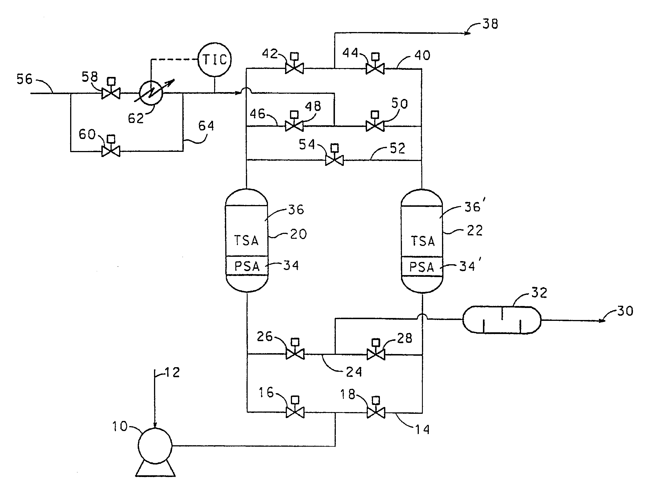
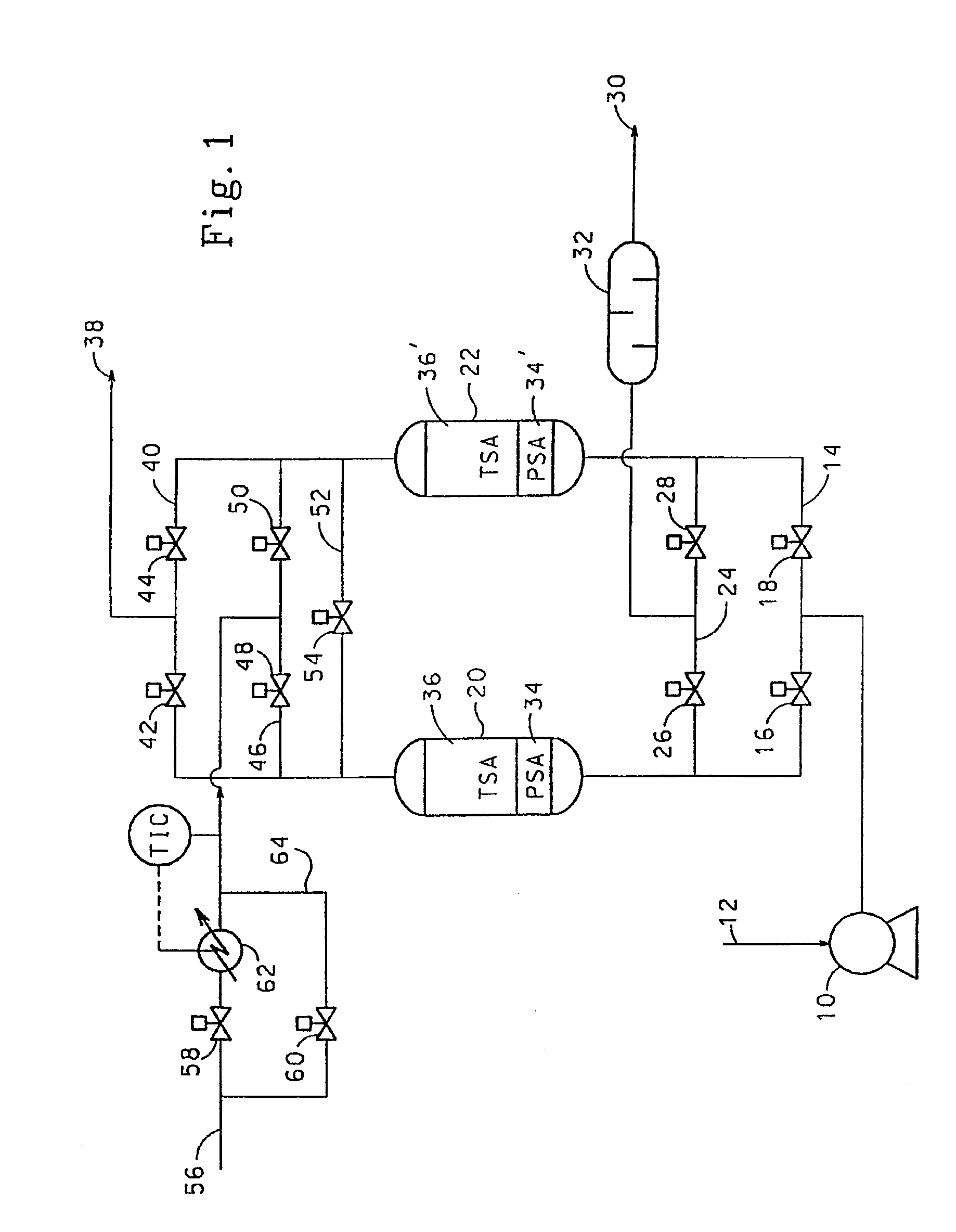
[0087]Two bed cyclic experiments for the removal of trace impurities from air were carried out in vessels 0.2 m in diameter. The length of the total adsorbent bed was 2 m. The feed air was saturated with water at feed conditions and contained 380 ppm CO2 and 0.3 ppm N2O. In all cases, the feed end of the adsorbent bed contained activated alumina (Alcan AA-300). Where present, the product end of the bed contained 13X zeolite (Zeochem Z10-02, Si / Al=1.15). The cycle tested is shown in Table 6 below:

[0088]

TABLE 6Feed time35 minHeat time at 70° C.10 minCool time at 36° C.19 minSwitch time (Depressurisation and6 minrepressurisation)Feed temperature36° C.Feed pressure7.3 bara (730 kPa)Purge / air ratio (molar basis)0.45Regeneration pressure1.25 bara (125 kPa)Feed flow rate6.0 kmol / h

[0089]The ratio of alumina to 13X in the adsorbent bed was varied and the average exit CO2 breakthrough le...

example 5

Effect of Zeolite Type

[0093]The effect of zeolite type was investigated in the experimental unit described in Example 4. In place of the 13X zeolite, CaX zeolite (Ceca G586) and 5A zeolite (UOP KEG 410) were used. The CaX zeolite is 86% Ca exchanged X zeolite, and the 5A zeolite is 74% Ca exchanged A zeolite. Comparison experiments were conducted with bed loadings of 75% activated alumina (Alcan AA-300) and 25% zeolite.

[0094]Tests conducted with CaX as the final adsorbent layer were not successful. The average CO2 content in the gas exiting the adsorption vessel never reached the 50 ppb time average target. It appears that CaX adsorbs CO2 too strongly for this application. CaX has, however, been taught in the prior art as the preferred adsorbent for simultaneous CO2 and N2O removal from ambient air in TSA applications where regeneration temperatures in excess of 80° C. are used.

[0095]In example 4, it was shown that when the bed contained 25% 13X zeolite, the level of N2O removal fro...

example 6

Effect of Alumina Type

[0096]The experimental unit described in Example 4 was used, with the experimental conditions given in Table 8 below. In these two tests, the volumetric alumina / 13X layering was kept at 75% alumina / 25% zeolite, and in both cases the 13X zeolite used was Zeochem Z10-02. In one case unimpregnated alumina (Alcan AA-300) was used, and in the other impregnated alumina (Alcan AA-320 with 5 wt % K2CO3) was used. Time averaged CO2 breakthrough level during these tests was 20 ppb.

[0097]

TABLE 8Feed time35 minHeat time at 70° C.10 minCool time at 50° C.15 minSwitch time (depressurisation and10 minrepressurisation)Feed temperature50° C.Feed pressure5.0 bara (500 kPa)Purge / air ratio (molar basis)0.50Regeneration pressure1.25 bara (125 kPa)Feed flow rate3.4 kmol / h

[0098]The results of the testing showed that the bed that contained the K2CO3-impregnated alumina had significantly higher N2O removal than the bed that used the unimpregnated alumina. The bed with the impregnated a...


PUM

PropertyMeasurementUnit
Henry's Law constantaaaaaaaaaa
temperatureaaaaaaaaaa

Abstract

Reduction of water, CO2 and N2O in an air stream comprising: passing said air stream at a feed temperature through a first adsorbent, whose Henry's Law selectivity for CO2 / N2O is at least 12.5, and a second adsorbent, whose Henry's Law constant for CO2 is less than 1020 mmol / g / atom and whose Henry's Law selectivity for CO2 / N2O is at most 5; and passing a heated regenerating gas at a temperature which is between 20° C. and 80° C. to at least the second adsorbent, and passing a second regenerating gas at a temperature less than the temperature of the heated regenerating gas to the first and second adsorbents in a direction opposite to the feed direction; the second adsorbent occupying from 25% to 40% of the total volume of the adsorbents, and the temperature of the heated regenerating gas being 10° C. to 60° C. higher than the feed temperature.

Description

BACKGROUND OF THE INVENTION[0001]The invention relates to the removal of water, carbon dioxide and nitrous oxide, and optionally also hydrocarbons, from an air stream prior to cryogenic air separation.[0002]The cryogenic separation of air requires a pre-purification step for the removal of both high-boiling and hazardous materials. Principal high-boiling air components include water and carbon dioxide. If removal of these impurities from ambient feed air is not achieved, then water and carbon dioxide will freeze out in cold sections of the separation process, such as heat exchangers and the LOX sump. This will cause pressure drop, flow variations and operational problems. Various hazardous materials have also to be recovered including acetylene and other hydrocarbons. The high boiling hydrocarbons, if not removed, will concentrate in the LOX section of the column, resulting in a potential explosive hazard.[0003]It is known that oxides of nitrogen should be removed also. A minor air ...

Claims


Application Information

Patent Timeline
Patent Type & Authority Patents(United States)
IPC IPC(8): B01D53/04B01D53/047
CPCB01D2257/504Y02C10/08B01D53/047B01D2257/402B01D2259/4146B01D2253/1085B01D53/0462Y02C20/10Y02C20/40
Inventor GOLDEN, CHRISTOPHER TIMOTHYKALBASSI, MOHAMMAD ALIRAISWELL, CHRISTOPHER JAMESWAWERU, CHRISTINEPOLLOCK, MICHAELA
Owner AIR PROD & CHEM INC
Why Eureka
Try Eureka