
Non-photosensitive siloxane coating for processing hydrophobic photoimageable nozzle plate

a technology of hydrophobic and photoimageable nozzles, which is applied in the field of microfluid ejection devices, can solve the problems of significant device contamination threat, phase or layer separation, adversely affecting the size and placement accuracy of fluid droplets ejected from the ejection head, etc., and achieves stable hydrophobic properties and improved mechanical properties.

Active Publication Date: 2014-05-20
FUNAI ELECTRIC CO LTD
View PDF8 Cites 0 Cited by
  • Summary
  • Abstract
  • Description
  • Claims
  • Application Information

AI Technical Summary

Benefits of technology

The patent describes a method for creating a patterned layer of photoresist (a material used in electronic devices) on a micro-fluid ejection head. This method results in an improved patterned layer with better mechanical properties and stable hydrophobic properties, which overcomes shortcomings of previous methods. This patent describes a technical improvement in the field of micro-fluid ejection heads.

Problems solved by technology

Such accumulation of fluid on the nozzle plate may adversely affect both the size and placement accuracy of the fluid droplets ejected from the ejection head.
However, this type of dual layer hPINP manufactured either through liquid formulation or wafer level processed dry film laminates possess material incompatibility issues which inherently may lead to phase or layer separation.
The extra post-nozzle-formation processing step required to generate the hydrophobic layer on the nozzle plate surface exposes the micro-fluid ejection head to significant threat of device contamination.
Furthermore, the formed hydrophobic layer may lack good mechanical properties, and the hydrophobic characteristic of the nozzle plate may not be sustained for an extended period of time.

Method used


Image

  • Non-photosensitive siloxane coating for processing hydrophobic photoimageable nozzle plate
  • Non-photosensitive siloxane coating for processing hydrophobic photoimageable nozzle plate
  • Non-photosensitive siloxane coating for processing hydrophobic photoimageable nozzle plate

Examples


Embodiment Construction

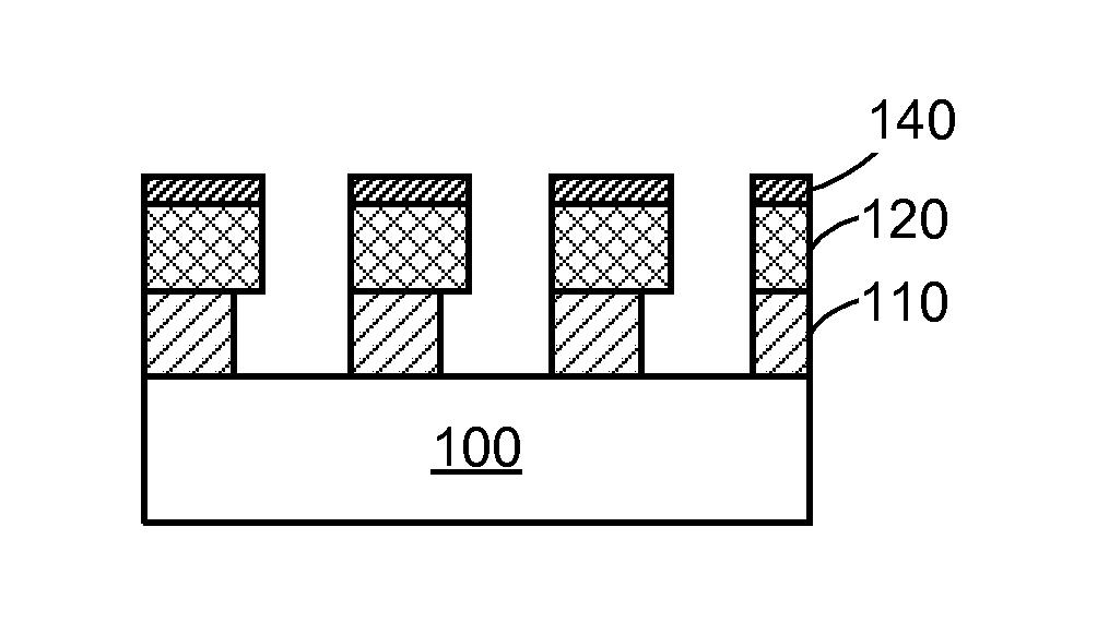
[0017]It is to be understood that the invention is not limited in its application to the details of construction and the arrangement of components set forth in the following description or illustrated in the drawings. The invention is capable of other embodiments and of being practiced or of being carried out in various ways. Also, it is to be understood that the phraseology and terminology used herein is for the purpose of description and should not be regarded as limiting. The use of “including,”“comprising,” or “having” and variations thereof herein is meant to encompass the items listed thereafter and equivalents thereof as well as additional items. Further, the terms “a” and “an” herein do not denote a limitation of quantity, but rather denote the presence of at least one of the referenced item.

[0018]Reference will now be made in detail to the example embodiment(s), as illustrated in the accompanying drawings. Whenever possible, the same reference numerals will be used througho...


PUM

PropertyMeasurementUnit
temperatureaaaaaaaaaa
hydrophobicaaaaaaaaaa
polymericaaaaaaaaaa

Abstract

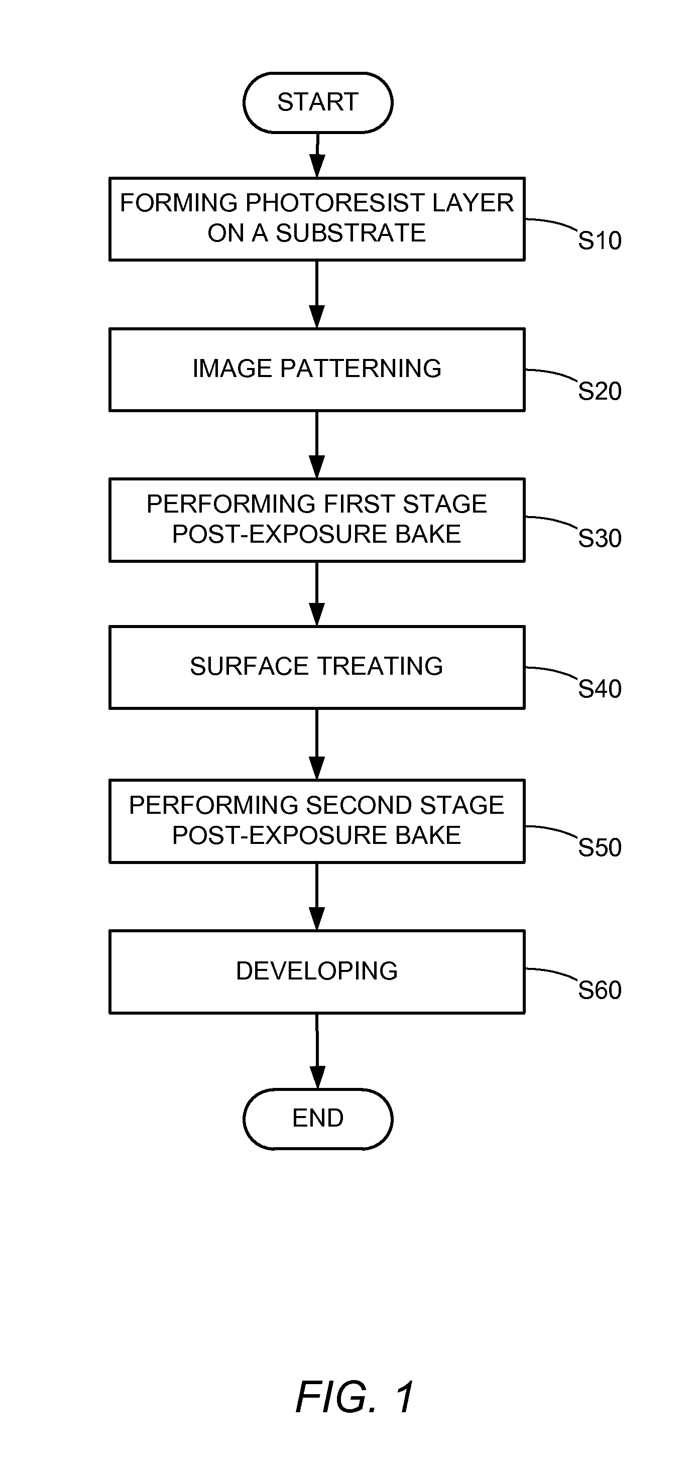
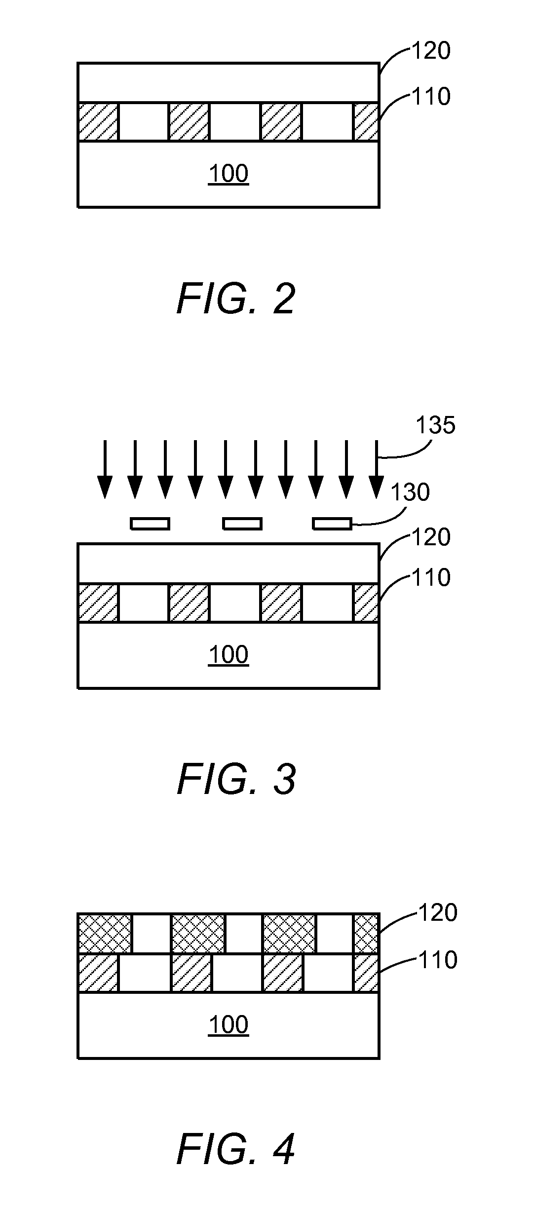
A method of forming a patterned photoresist layer having a hydrophobic surface is provided. The method includes forming a photoresist layer on a substrate and image patterning. The photoresist layer may comprise a polymeric material. The imaged photoresist layer may then undergo a two-stage post-exposure bake. A surface treatment may be performed on the photoresist layer in between the two-stage post-exposure bake. The surface treatment may include applying a siloxane solution on a partially post-exposure baked photoresist layer. The post-exposure baked photoresist layer may then be developed to form the patterned photoresist layer. The method may be used to form a hydrophobic photoimageable nozzle plate of a micro-fluid ejection head having improved mechanical properties and stable hydrophobic properties.

Description

CROSS REFERENCES TO RELATED APPLICATIONS[0001]None.STATEMENT REGARDING FEDERALLY SPONSORED RESEARCH OR DEVELOPMENT[0002]None.REFERENCE TO SEQUENTIAL LISTING, ETC[0003]None.BACKGROUND[0004]1. Field of the Disclosure[0005]The present disclosure generally relates to micro-fluid ejection devices and, more particularly, to a micro-fluid ejection head having hydrophobic nozzle plate.[0006]2. Description of the Related Art[0007]The degree of hydrophobicity / hydrophilicity of a micro-fluid ejection head plays an important role in the overall performance of a micro-fluid ejection device. For example, as the size of the nozzles in the nozzle plate shrinks in order to get smaller droplet sizes, the sensitivity of the fluid ejected to the surface energy of the nozzle plate increases dramatically. One factor that contributes to this phenomenon is the accumulation of fluid or other contaminants on the nozzle plate surface. Such accumulation of fluid on the nozzle plate may adversely affect both th...

Claims


Application Information

Patent Timeline
Patent Type & Authority Patents(United States)
IPC IPC(8): G03F7/26
CPCB05B1/02G03F7/265G03F7/38B01L3/502707G03F7/20
Inventor BERNARD, DAVIDDRYER, PAULMANSDORF, BARTWU, XIAOMING
Owner FUNAI ELECTRIC CO LTD
Learn More