Package carrier and manufacturing method thereof

a packaging and manufacturing method technology, applied in the direction of printed circuit aspects, printed circuit non-printed electric components, semiconductor/solid-state device details, etc., can solve the problems of reduced layout space, difficulty in heat dissipation, and inability to meet the miniaturization requirements of existing electronic products, so as to achieve favorable heat dissipation performance and small package thickness

Active Publication Date: 2014-04-22
SUBTRON TECH
View PDF11 Cites 4 Cited by
  • Summary
  • Abstract
  • Description
  • Claims
  • Application Information

AI Technical Summary

Benefits of technology

[0007]The invention is directed to a package carrier with favorable heat-dissipation performance and small package thickness.
[0019]Based on the above, the package carrier described herein has the heat-conducting device, and the heat-conducting device is embedded in the substrate. Therefore, when a heat-generating device is configured on the package carrier, heat generated by the heat-generating device may be rapidly transmitted to external surroundings through the heat-conducting device, so as to effectively dissipate the heat generated by the heat-generating device and further improve efficiency and extend the life span of the heat-generating device. Moreover, the electronic device provided in an embodiment of the invention is embedded in the substrate, and thus the package carrier described herein may have small package thickness and large layout space.

Problems solved by technology

Nonetheless, if the electronic devices are all configured on the package carrier, the area occupied by the electronic devices may increase, the layout space may decrease, and the miniaturization requirement for the existing electronic products may not be satisfied.
Due to the unfavorable heat conductivity of the adhesion layer and the insulation layer, the thermal resistance may increase when the heat generated by the electronic devices is transmitted to the heat-dissipation blocks through the insulation layer and the adhesion layer, which leads to difficulty in heat dissipation.

Method used


Image

  • Package carrier and manufacturing method thereof
  • Package carrier and manufacturing method thereof
  • Package carrier and manufacturing method thereof

Examples


Embodiment Construction

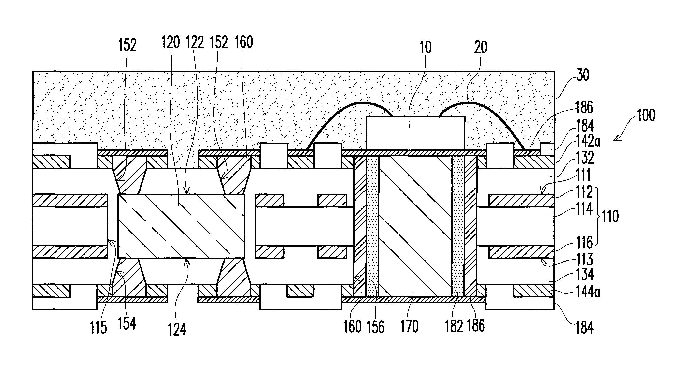
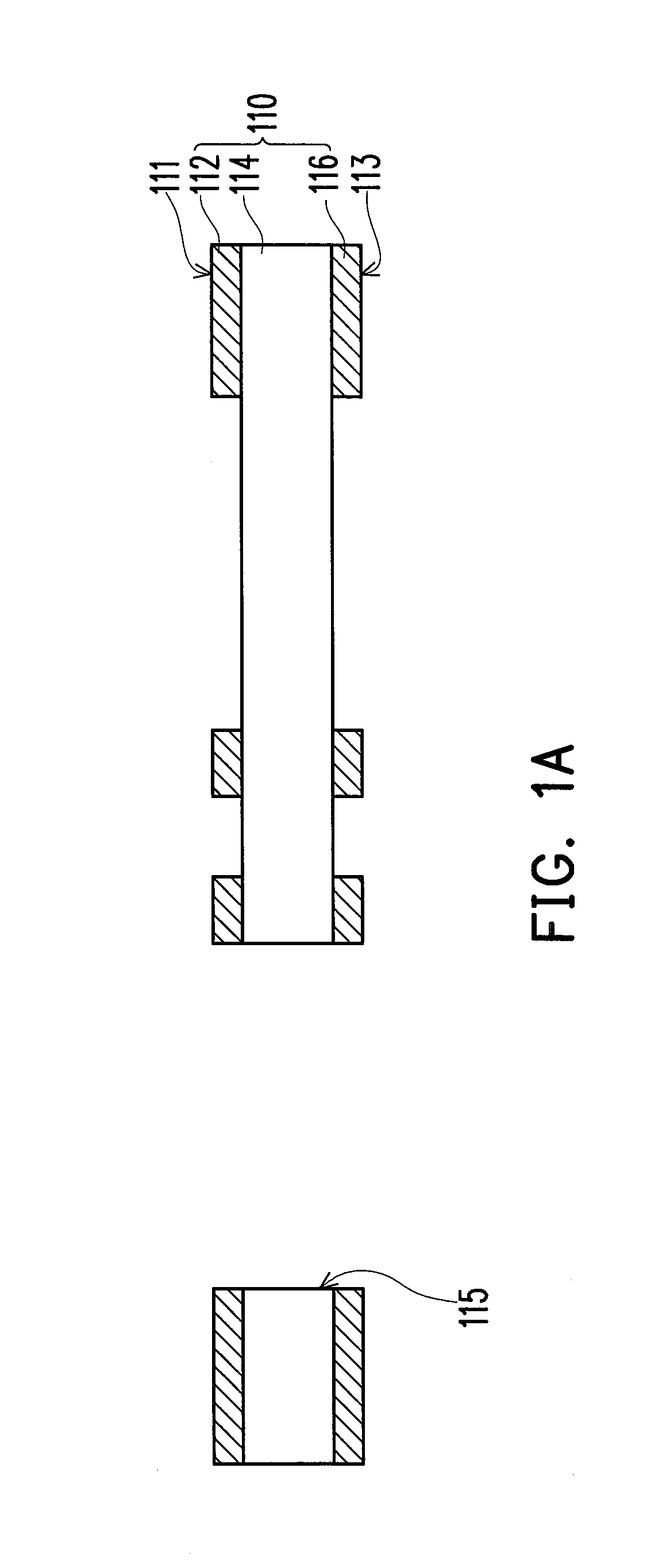
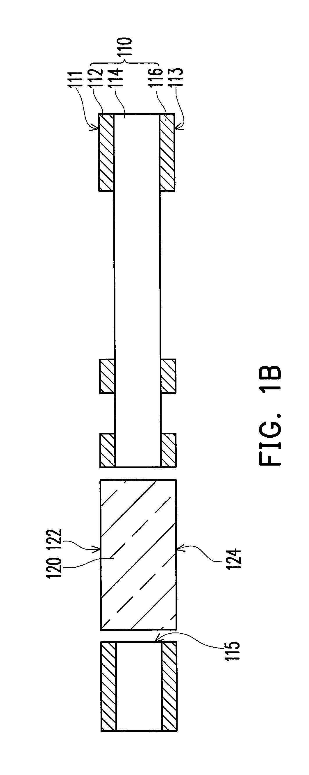
[0024]FIG. 1A to FIG. 1G are schematic cross-sectional views illustrating a manufacturing method of a package carrier according to an embodiment of the invention. As shown in FIG. 1A, in the manufacturing method of the package carrier according to the present embodiment, a substrate 110 is provided. The substrate 110 has an upper surface 111, a lower surface 113 opposite to the upper surface 111, and an opening 115 communicating the upper surface 111 and the lower surface 113. According to the present embodiment, the substrate 110 is composed of a first copper foil layer 112, a core dielectric layer 114, and a second copper foil layer 116, for instance, and the core dielectric layer 114 is disposed between the first copper foil layer 112 and the second copper foil layer 116. That is, the substrate 110 described in the present embodiment is a double-sided board. Certainly, in other embodiments, the substrate 110 may be a multi-layer board or a glass fiber (FR4) substrate. The type of...


PUM

PropertyMeasurementUnit
densityaaaaaaaaaa
conductiveaaaaaaaaaa
heat dissipation performanceaaaaaaaaaa

Abstract

In a manufacturing method of a package carrier, a substrate having an upper surface, a lower surface, and an opening communicating the two surfaces is provided. An electronic device is disposed inside the opening. A first insulation layer and a superimposed first metal layer are laminated on the upper surface; a second insulation layer and a superimposed second metal layer are laminated on the lower surface. The opening is filled with the first and second insulation layers. First blind holes, second blind holes, and a heat-dissipation channel are formed. A third metal layer is formed on the first and second blind holes and an inner wall of the heat-dissipation channel. A heat-conducting device is disposed inside the heat-dissipation channel and fixed into the heat-dissipation channel via an insulation material. The first and second metal layers are patterned to form a first patterned metal layer and a second patterned metal layer.

Description

CROSS-REFERENCE TO RELATED APPLICATION[0001]This application claims the priority benefit of Taiwan application serial no. 101113270, filed on Apr. 13, 2012. The entirety of the above-mentioned patent application is hereby incorporated by reference herein and made a part of this specification.BACKGROUND OF THE INVENTION[0002]1. Field of the Invention[0003]The invention relates to a package structure and a manufacturing method thereof. More particularly, the invention relates to a package carrier and a manufacturing method thereof.[0004]2. Description of Related Art[0005]In recent years, as the electronic technology advances at every moment and the high-tech electronic industry continues burgeoning, electronic products have been developing toward the trend of fast processing speed, multi-functionality, high density, compactness, and low prices. A package carrier is often configured in the electronic product. The package carrier not only has conductive circuits but also carries electro...

Claims


Application Information

Patent Timeline
Patent Type & Authority Patents(United States)
IPC IPC(8): H05K1/00H05K1/11H05K1/18
CPCH01L23/5389H01L23/5383H01L21/48H01L2224/48091H01L23/3121H01L23/3677H05K2203/1469H05K2201/09581H05K2201/10416H01L2224/48228H05K1/0204H05K3/4602H05K1/185H01L25/16H01L25/167H01L33/64H01L2924/181Y10T29/49139H01L2924/00014H01L2924/00012
Inventor SUN, SHIH-HAO
Owner SUBTRON TECH
Why Eureka
Try Eureka