Porous polymer and process for producing the same

a porous polymer and polymer technology, applied in the field of polymeric porous materials, can solve the problems of poor solvent separation capacity, lower separation efficiency, and poor aggregated polymer molecules that evolved from monomers, and achieve the effect of superior separation capacity

Inactive Publication Date: 2014-04-15
NAT UNIV KYOTO INST OF TECH +1
View PDF12 Cites 0 Cited by
  • Summary
  • Abstract
  • Description
  • Claims
  • Application Information

AI Technical Summary

Benefits of technology

[0026]The polymeric porous material according to the present invention has a uniform structure, regular pores and a permeability suitable for flowing a mobile phase. Therefore, the polymeric porous material according to the present invention can show a superior separation capacity when it is used as a polymeric separation medium filled in a liquid chromatography column.

Problems solved by technology

However, polymer molecules evolved from a monomer tend to be aggregated in a poor solvent, since the effect of van der Waals forces between the polymer molecules is greater than the steric hindrance effect.
There are some problems with such an aggregate that the separation efficiency becomes lower, because the aggregate has a labyrinth of macro through-pore channels, and the eddy diffusion of solute becomes higher; the aggregate is mechanically fragile, and the morphological stability thereof is as low as a change in porosity due to a compressive effect is caused when a column filled with the aggregate is subjected to a high back pressure; the separation capacity of solute becomes lower, because the aggregate has a small amount of mesopores having a nanometer diameter and a extremely low specific surface area of pores; and the like.
In general, when a solution of low molecular weight substance is subjected to a rapid temperature change (rapid cooling or rapid heating) into an unstable area where two phases are coexisted, the spinodal decomposition is rapidly caused.

Method used


Image

  • Porous polymer and process for producing the same
  • Porous polymer and process for producing the same
  • Porous polymer and process for producing the same

Examples


example 1

[0108]Into a test tube (internal diameter 10 mm, length 200 mm) was added 1.86 ml of a distilled chlorobenzene (χ about 0.37). Thereto was added 55.8 mg of a flake powder of ultrahigh molecular weight polystyrene (Mw=3,840,000, Mw / Mn=1.04; Tosoh) at a room temperature. The mixture was gently agitated with a spatula to diffuse the polystyrene flake, and then the test tube was immersed in an ultrasonic agitation bath (Branson Ultrasonic Cleaner) for 10 minutes. After that, the test tube was let stand for 24 hours at a room temperature to give a transparent polymer porogen solution.

[0109]Next, 10 mg of 2,2′-azobisisobutyronitrile (Mw=164.21, 98%, Nacalai Tesque) was added to the polymer porogen solution, and dissolved in the solution by handshaking. Then, 1 ml of glycerol dimethacrylate (GDMA; KYOEISHA CHEMICAL, GP-101 P, molecular weight 227) was added to the solution to give a uniform transparent polymerization solution. After bubbling this polymerization solution with an argon gas f...

example 2

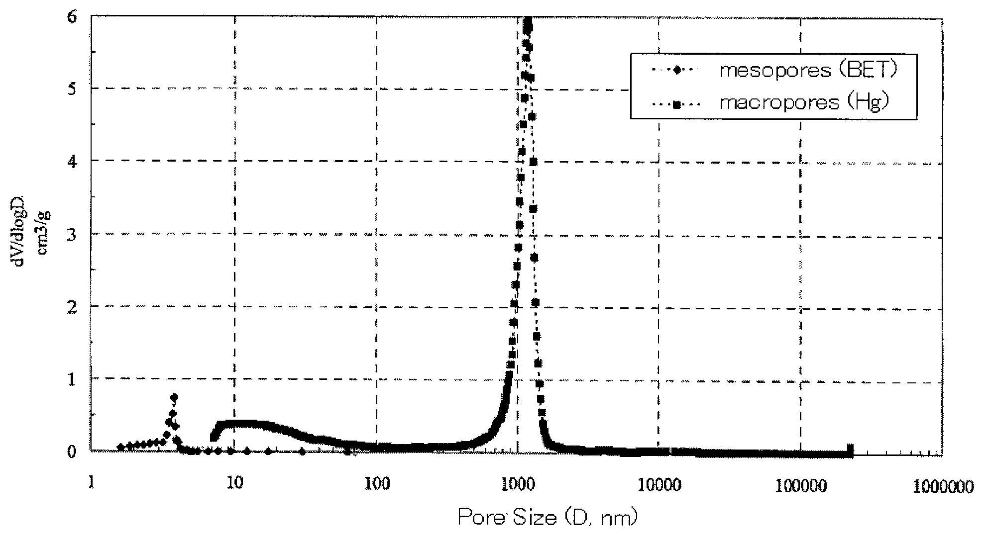
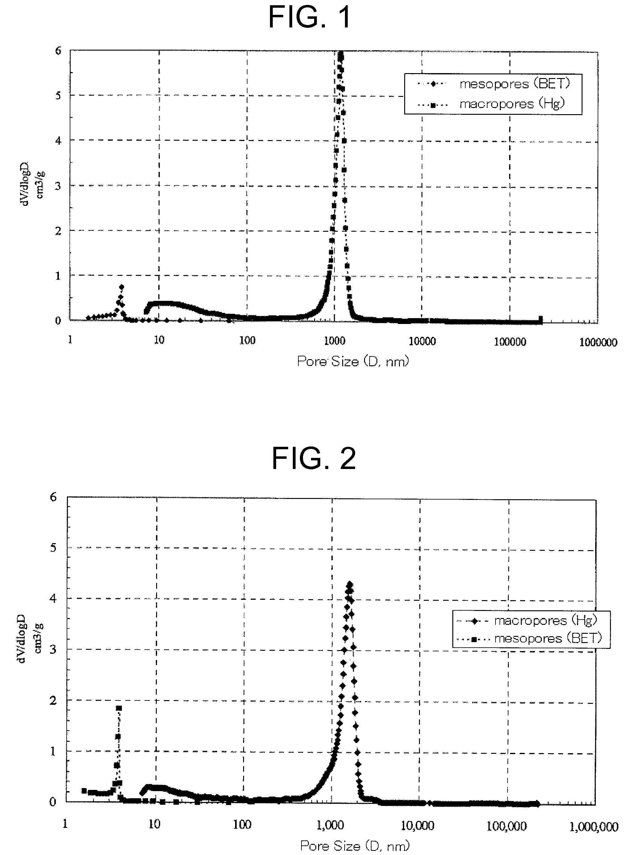
[0112]The polymerization was carried out in the same manner as in Example 1 except that GDMA was changed to ethylene dimethacrylate (EDMA; χ about 0.36, KYOEISHA CHEMICAL, molecular weight 198, distilled at 64° C., 25 mmHg), 2,2′-azobisisobutyronitrile was changed to 2,2′-azobis(2,4-dimethyl)valeronitrile (Mw=248.37, 95%, WAKO chemicals). As a result, the test tube was filled up to a height of 4 cm from its bottom with a white solid. After drying the solid, the mesopores and the macropores of the dried sample were measured in the same manner as in Example 1. From the measurement results, the proportion of the specific surface area of the macropores to the specific surface area of all pores was calculated. The results are shown in Table 1. The pore size distribution is shown in FIG. 2. As in the case of Example 1, a bimodal distribution with sharp peaks located at 4 nm in a mesopore range and located within a range from 1 to 2 μm in a macropore range was observed.

example 3

[0113]A polymerization solution of GDMA was prepared in the same manner as in Example 2 except that EDMA was changed to GDMA, and stored in a refrigerator. Then, a fused silica capillary coated with polyimide (internal diameter 200 μm) was cut as a coil having a length of about 180 cm, and 1 N aqueous NaOH solution was injected into the coil by a syringe. After sealing the both ends of the capillary coil, the coil was treated in a water bath at 60° C. for 1 hour. Then, the capillary coil was sequentially washed with excessive amounts of acetone and pure water in repeating fashion. The washed capillary coil was dried by a hot-air dryer at 160° C. for 24 hours.

[0114]Then, the above-mentioned stored GDMA solution was charged into the capillary coil by using a syringe pump (Harvard Apparatus Model 11) at a room temperature. After that, the both ends of the capillary coil were immediately sealed with a parafilm. Then, the polymerization was carried out in a water bath set at 60° C. for 2...


PUM

PropertyMeasurementUnit
pore sizeaaaaaaaaaa
pore sizeaaaaaaaaaa
pore sizeaaaaaaaaaa

Abstract

The present invention relates to a polymeric porous material characterized in that: the porous material has a bimodal pore size distribution attributable to macropores having a pore size of at least 50 nm and mesopores having a pore size of from 2 nm to less than 50 nm, the proportion of the specific surface area of the macropores to the specific surface area of all pores of the porous material is at least 10%, and the porous material is produced by (1) polymerizing a monomer in the presence of a polymerization initiator using as a porogen a solution obtained by dissolving a polymer having a weight-average molecular weight of at least 100,000 and a molecular weight distribution Mw / Mn of not more than 1.5 in a good solvent for the monomer, and (2) removing the porogen from the resultant product.

Description

TECHNICAL FIELD[0001]The present application was filed claiming the priority of Japanese Patent Application No. 2005-151077, the entire content of which is herein incorporated by reference.[0002]The present invention relates to a polymeric porous material useful as a polymeric separation medium for filling a liquid chromatography column and the like.BACKGROUND ART[0003]Conventionally, methods comprising polymerizing a crosslinkable monomer in situ in a column with a poor solvent as a porogen (pore-forming agent) have been predominantly used for preparing a polymer-based monolithic separation medium for liquid chromatography. For example, Patent Literature 1 describes a process for producing a liquid chromatography column containing a polymer having pores having a diameter of less than 200 nm and pores having a diameter of not less than 600 nm, which comprises reacting a polymerization mixture containing a hydrophobic vinyl monomer, a radical initiator, and a poor solvent for the vin...

Claims


Application Information

Patent Timeline
Patent Type & Authority Patents(United States)
IPC IPC(8): B01J20/30B01J20/28B01D15/08G01N30/02B01D15/38
CPCB01J20/28085B01J20/285C08J9/26B01J20/305B01J20/28054B01D15/3842C08J2201/046B01J20/28083B01J20/28092C08J2205/048Y10T428/249978
Inventor HOSOYA, KENAOKI, HIROSHIISHIZUKA, NORIOYAMAMOTO, KATSUYA
Owner NAT UNIV KYOTO INST OF TECH
Why Eureka
Try Eureka