
Nitratable steel piston rings and steel cylindrical sleeves, and casting method for the production thereof

a technology of steel cylindrical sleeves and piston rings, which is applied in the direction of botany apparatus and processes, furnace types, engines without rotary main shafts, etc., can solve the problems of engine damage, engine wear, and engine damage, and achieve long-term high performance, reduce oil consumption, and reduce the tendency to change the shape

Inactive Publication Date: 2014-02-11
FEDERAL MOGUL BURSCHEID
View PDF12 Cites 2 Cited by
  • Summary
  • Abstract
  • Description
  • Claims
  • Application Information

AI Technical Summary

Benefits of technology

[0029]It is assumed that the good nitridability of the piston rings and cylinder liners of the invention is due to the 4.0-20.0 weight % chromium content. In the nitriding process, chromium forms very hard nitrides. While adding chromium to a steel composition would normally raise the austenite transition temperature of the material further and thus would cause its hardenability to deteriorate further, in the present invention it was observed that adding 2.0-12.0 weight % of nickel counteracts this rise in the austenite transition temperature. In this manner, the invention prevents an increase in the austenite transition temperature from nullifying the better hardenability of the surface of the material obtainable because of the improved nitridability of the steel composition by means of a simultaneous reduction in the hardenability of the main body.
[0036]The nitrided steel piston rings and steel cylinder liners of the invention have a reduced tendency to change their shape when heated strongly, and thus provide long-term high performance and, moreover, reduced oil consumption.
[0037]The nitrided steel piston rings and steel cylinder liners of the invention also have the advantage that they can be manufactured using machinery and technology for manufacturing cast iron parts. In addition, the manufacturing costs correspond to those of cast iron piston rings or grey cast iron cylinder liners, providing cost savings for the manufacturer and improving margins. Similarly, the material parameters can be adjusted independently of the supplier.

Problems solved by technology

The mutual sliding of these components against each other results in a greater or lesser amount of wear, depending on the material; if it runs dry, this can lead to so-called fretting, scoring and finally destruction of the engine.
Further, in extreme cases, the piston ring might no longer bear evenly on the cylinder liner and then even more gas can gain ingress into the crankcase.
Prior art cast iron materials, however, are at great risk of breaking; in fact, when using current materials, the rings frequently break.
Increased mechanico-dynamic loads result in shorter service lifetimes for piston rings and cylinder liners.
Severe wear and corrosion occurs on the running faces and flanks.
Higher ignition pressures, reduced emissions and direct fuel injection mean increased loads on the piston rings.
This results in damage and a build-up of piston material, especially on the lower piston ring flank.
However, using such steels suffers from the disadvantage that the manufacturing costs are significantly higher than those of cast iron components.
A further disadvantage of the manufacture of piston rings from steel is that beyond a certain diameter, ring manufacture (coiling) from steel wire is no longer possible.
A lower casting temperature also results in a lower stress on the material of the mould (erosion, gas porosity, sand inclusions) and the furnace and also results in lower melting costs.
However, the silicon present in larger quantities has a negative influence on the hardenability of the material since its austenite transition temperature, “Ac3”, is increased.
However, it has been shown that prior art high silicon steel castings have poor nitridability.

Method used


Image

  • Nitratable steel piston rings and steel cylindrical sleeves, and casting method for the production thereof
  • Nitratable steel piston rings and steel cylindrical sleeves, and casting method for the production thereof

Examples


example

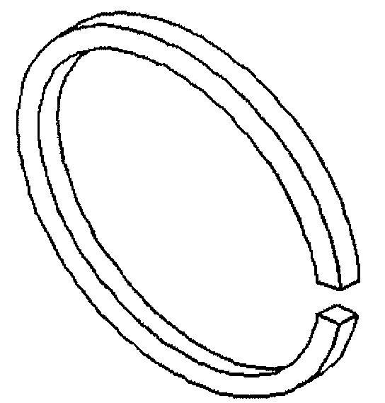
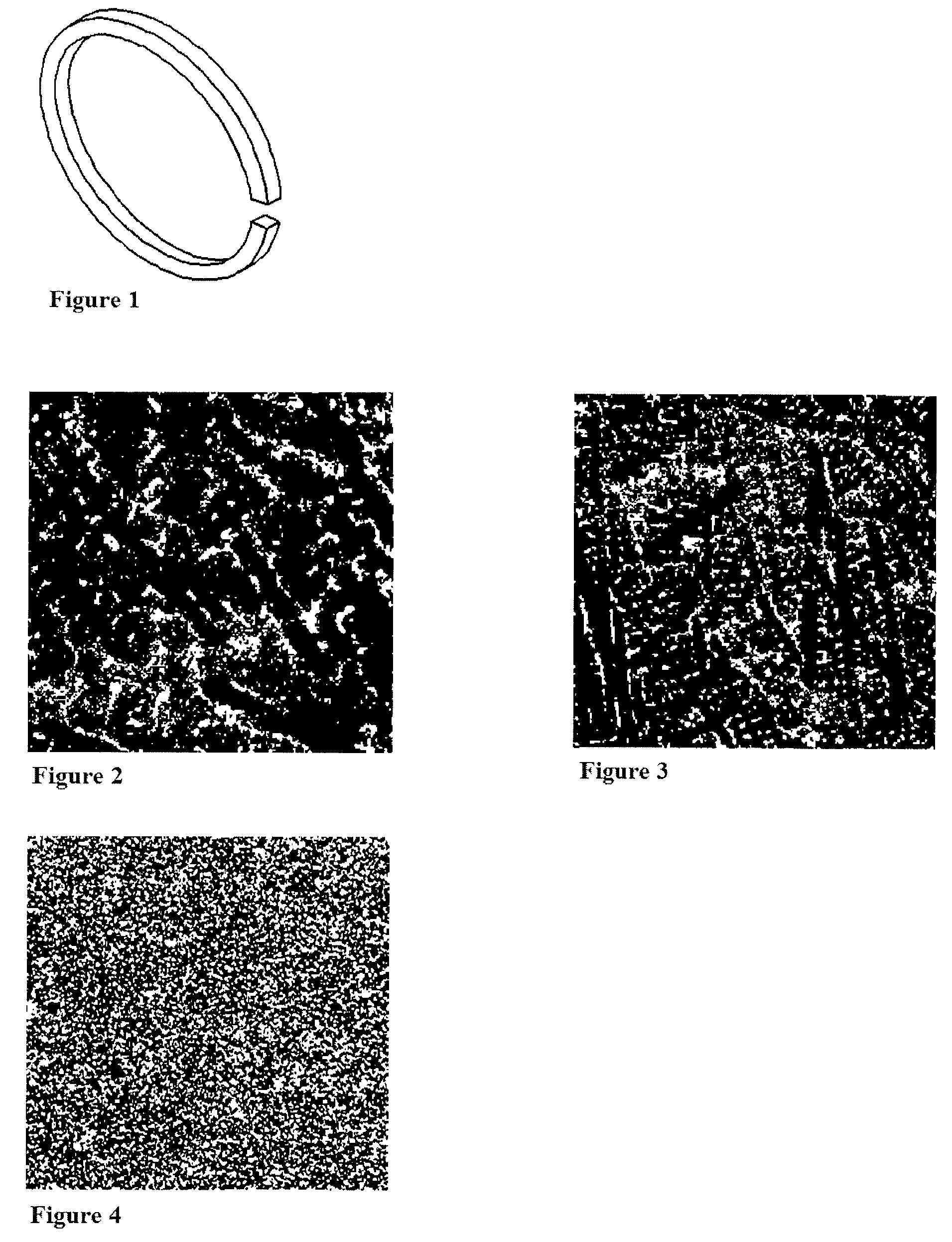
[0055]A piston ring (see FIG. 1) was manufactured from a highly nitridable steel composition in accordance with the invention having the following composition:

[0056]

B:0.001weight %C:0.8weight %Cr:13.0weight %Cu:0.05weight %Mn:0.3weight %Mo:0.5weight %Nb:0.002weight %Ni:2.1weight %P:0.041weight %Pb:0.16weight %S:0.009weight %Si:3.0weight %Sn:0.001weight %Ti:0.003weight %V:0.11weight %W:0.003weight %Fe:remainder

[0057]It was obtained by producing a molten mass from the starting materials (steel scrap, return scrap and alloying substances) and casting the melt into a prepared green sand mould. Next, the mould was emptied and the piston ring obtained was cleaned. The piston ring was then quenched and tempered. This was accomplished by austenitization above the Ac3 temperature of the steel composition, quenching in oil and tempering at a temperature in the range 400° C. to 700° C. in a controlled atmosphere furnace.

[0058]Finally, the surface of the piston ring obtained was nitrided. Altho...


PUM

PropertyMeasurementUnit
temperatureaaaaaaaaaa
melting pointaaaaaaaaaa

Abstract

A steel piston ring and a steel cylinder liner are described which comprise as the main body a steel composition which has good nitridability. The steel composition consists of the following elements: 0-0.5 weight % B, 0.5-1.2 weight % C, 4.0-20.0 weight % Cr, 0-2.0 weight % Cu, 45.30-91.25 weight % Fe, 0.1-3.0 weight % Mn, 0.1-3.0 weight % Mo, 0-0.05 weight % Nb, 2.0-12.0 weight % Ni, 0-0.1 weight % P, 0-0.05 weight % Pb, 0-0.05 weight % S, 2.0-10.0 weight % Si, 0-0.05 weight % Sn, 0.05-2.0 weight % V, 0-0.2 weight % Ti and 0-0.5 weight % W. The steel piston ring and the steel cylinder liner can be manufactured in a casting process using the machinery and technology employed for the manufacture of cast iron parts.

Description

BACKGROUND OF THE INVENTION[0001]1. Technical Field[0002]The present invention relates to piston rings and cylinder liners which have good nitridability and can be manufactured in a casting process. Furthermore, the present invention relates to nitrided piston rings and cylinder liners which can be manufactured from the piston rings and cylinder liners with good nitridability of the invention. In addition, the present invention relates to a process for the manufacture of the piston rings and cylinder liners with good nitridability of the invention and to a process for the manufacture of nitrided piston rings and cylinder liners in accordance with the invention.[0003]2. Related Art[0004]In an internal combustion engine, piston rings seal the gap between the piston head and the cylinder wall of the combustion chamber. As the piston moves back and forth, one side of the piston ring slides with its outer circumferential surface against the cylinder wall in a permanently spring-loaded po...

Claims


Application Information

Patent Timeline
Patent Type & Authority Patents(United States)
IPC IPC(8): C21D9/00C22C38/46C21D9/40C23C8/26C22C38/34
CPCC22C38/46C22C38/44F16J10/04C22C38/34F16J9/26B22D13/00C22C38/02C22C38/42C22C38/48C22C38/50C22C38/54
Inventor PELSOECZY, LASZLO
Owner FEDERAL MOGUL BURSCHEID
Learn More