Eureka AIR delivers breakthrough ideas for toughest innovation challenges, trusted by R&D personnel around the world.

Systems and methods for VLAN tagging via cloud bridge

a technology of cloud bridge and vlan, applied in the field of data communication networks, can solve the problems of more difficult tasks such as maintaining the same configuration settings and seamless communication with virtual machines in the prior data center, and achieve the effect of facilitating the seamless transition of virtual machines

Active Publication Date: 2012-06-28
CITRIX SYST INC
View PDF5 Cites 79 Cited by
  • Summary
  • Abstract
  • Description
  • Claims
  • Application Information

AI Technical Summary

Benefits of technology

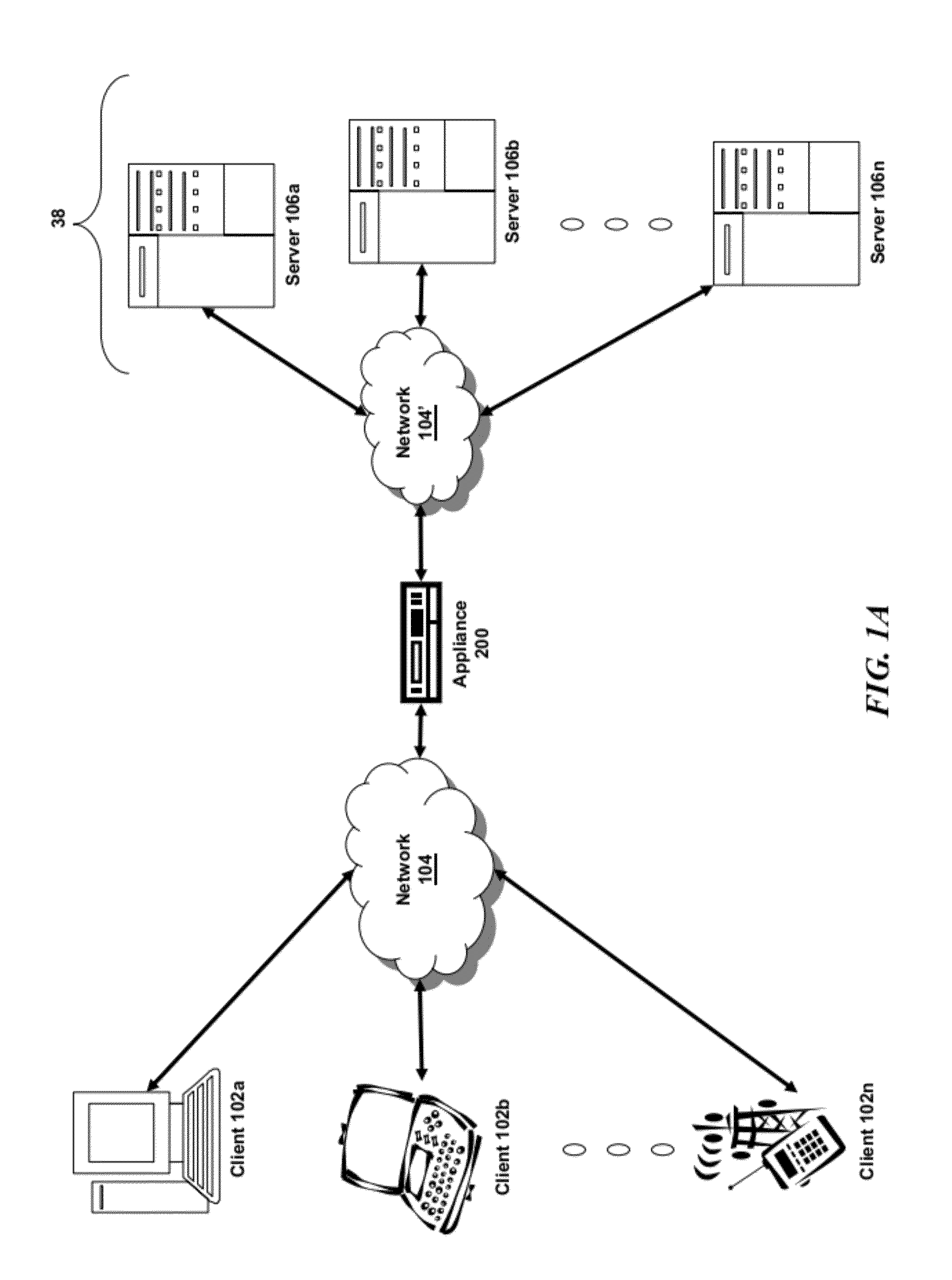
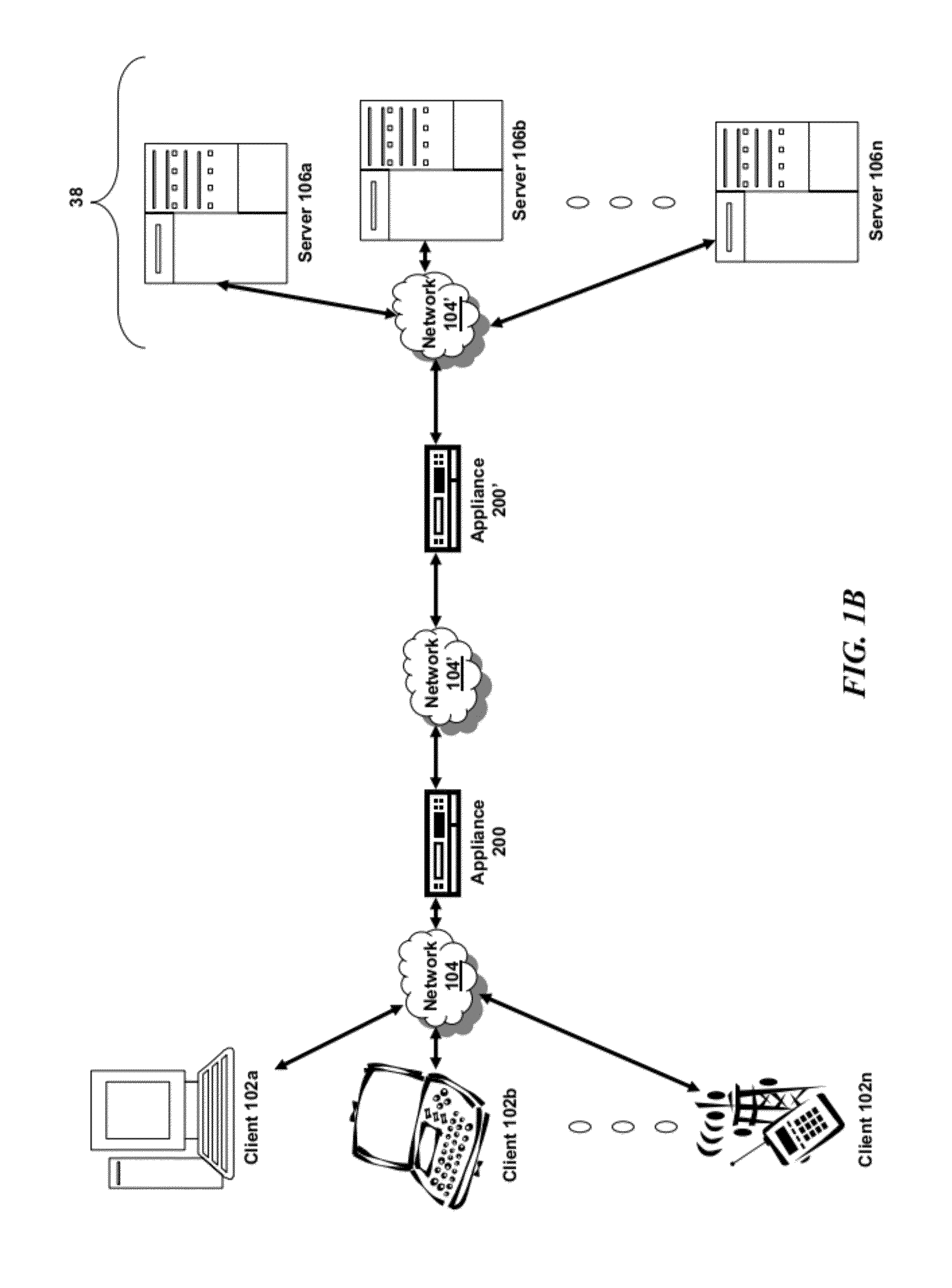
[0005]The present disclosure is directed towards using network appliances as a means to bridge, or tunnel, between and amongst either traditional “Premise” data centers, where virtual machines may be hosted locally or remotely on a plurality of physical machines, and connected to via private networks, or, increasingly common, “Cloud” data centers, where data center facilities are hosted virtually and accessible over the public Internet. According to embodiments of the present disclosure, appliances located in each data center can create a bridge, or tunnel, across the public Internet which allows communication amongst data centers. These appliances may also facilitate the seamless transition of a virtual machine from one data center to another, even when transitioning from a premise data center to a Cloud data center and communicating across the public Internet.

Problems solved by technology

However, if a virtual Machine is to be moved to a different data center or to a cloud-based data center, maintaining the same configuration settings and seamless communication with the virtual machines in the prior data center becomes a more difficult task.

Method used


Image

  • Systems and methods for VLAN tagging via cloud bridge
  • Systems and methods for VLAN tagging via cloud bridge
  • Systems and methods for VLAN tagging via cloud bridge

Examples


Embodiment Construction

[0037]For purposes of reading the description of the various embodiments below, the following descriptions of the sections of the specification and their respective contents may be helpful:[0038]Section A describes a network environment and computing environment which may be useful for practicing embodiments described herein;[0039]Section B describes embodiments of systems and methods for delivering a computing environment to a remote user;[0040]Section C describes embodiments of systems and methods for accelerating communications between a client and a server;[0041]Section D describes embodiments of systems and methods for virtualizing an application delivery controller;[0042]Section E describes embodiments of systems and methods for providing a multi-core architecture and environment; and[0043]Section F describes embodiments of systems and methods for VLAN tagging via cloud bridges and seamlessly integrating data centers across cloud bridges.

A. Network and Computing Environment

[00...


PUM


Abstract

The present disclosure is directed to supporting multiple virtual LANs (VLANs) via a single tunnel between intermediary devices. A first intermediary device of a first data center on a first network receives, from a second intermediary device of a second data center on a second network, an encapsulated packet via a tunnel established between the first intermediary device and the second intermediary device. The first intermediary device comprising a plurality of network interfaces, each corresponding to a virtual LAN (VLAN) network of a plurality of VLAN networks. The first intermediary device detects that the encapsulated packet has been tagged with virtual LAN (VLAN) information by the second intermediary device identifies a VLAN network of the plurality of VLAN networks and transmits a packet of the encapsulated packet via the network interface corresponding to the identified VLAN network.

Description

RELATED APPLICATIONS[0001]The present application claims priority to U.S. Provisional Patent Application No. 61 / 427,694, entitled “SYSTEMS AND METHODS FOR VLAN TAGGING VIA CLOUD BRIDGE”, filed Dec. 28, 2010, which is incorporated herein by reference in its entirety for all purposes.FIELD OF THE INVENTION[0002]The present application generally relates to data communication networks. In particular, the present application relates to systems and methods for creating cloud bridges between and amongst cloud data centers and supporting virtual LAN tagging in such deployments.BACKGROUND OF THE INVENTION[0003]Before the widespread deployment of virtualization, there was formerly a clear physical division between various data centers. Machines within a data center traditionally formed an intranet and had to engage in direct connectivity in order to talk to machines in a separate data center, for example by using L3 connectivity. Numerous switches, routers, load balancers, and firewalls facil...

Claims


Application Information

Patent Timeline
IPC IPC(8): H04L12/28H04L12/56H04L45/50
CPCH04L12/4641
Inventor GOEL, DEEPAKKURMA, JYOTHEESH
Owner CITRIX SYST INC
Why Eureka
Eureka Blog
Learn More