
Printing multi-channel image on web receiver

a multi-channel image and web receiver technology, applied in the field of printing images, can solve the problems of increasing waste and print cost, not providing positive control of the receiver, and the printhead cannot form part of the pulling apparatus, so as to reduce the waste of the receiver material, improve image quality, and maintain the effect of positive tension on the paper

Inactive Publication Date: 2013-12-31
EASTMAN KODAK CO
View PDF11 Cites 7 Cited by
  • Summary
  • Abstract
  • Description
  • Claims
  • Application Information

AI Technical Summary

Benefits of technology

This invention provides a non-contact, continuous-web printer that reduces waste of receiver material and improves image quality. It maintains positive tension on the paper during printing, allowing for smoother and more accurate images. It is not limited in the length of paper or size of cut sheets. The receiver only moves in one direction during printing, which can increase throughput. The movable transport can overcome the inertia of the supply of web receiver, resulting in a smaller, more responsive motor and a lower diameter take-up roll, reducing waste of receiver material. This invention is more compact and efficient than previous systems. The amount of leader in the invention is independent of the number of stations, which is useful for additive-fabrication schemes with multiple components.

Problems solved by technology

However, printing technologies such as inkjet printing use non-contact printheads, so the printhead cannot form part of the pulling apparatus.
Moreover, using a pulling mechanism downstream of the printhead results in the receiver between the printhead and the pulling mechanism being unprinted and discarded, increasing waste and print cost.
However, these schemes do not provide positive control of the receiver until it engages a pulling member sometime after printing begins.
This can result in variations in the spacing between the receiver and a non-contact printhead in the leading portion of the image, changing image attributes.
These changes can produce a visibly-objectionable difference between the portion of the image pushed past the printhead and the portion pulled past.
Pushing the web past the printhead over its entire length exacerbates these problems and can lead to receiver buckle, possibly contacting a non-contact printhead and damaging it (a “head strike”).

Method used


Image

  • Printing multi-channel image on web receiver
  • Printing multi-channel image on web receiver
  • Printing multi-channel image on web receiver

Examples


Embodiment Construction

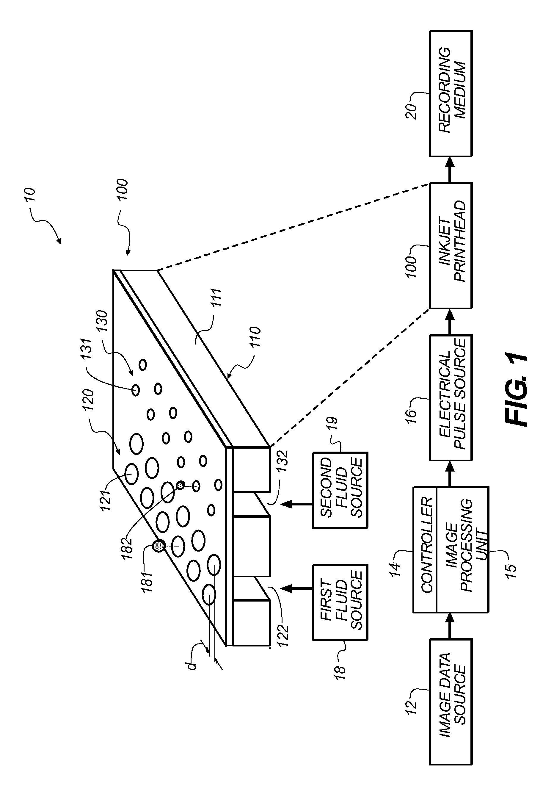
[0036]In the following description, some embodiments will be described in terms that would ordinarily be implemented as software programs. Those skilled in the art will readily recognize that the equivalent of such software can also be constructed in hardware. Because image manipulation algorithms and systems are well known, the present description will be directed in particular to algorithms and systems forming part of, or cooperating more directly with, systems and methods described herein. Other aspects of such algorithms and systems, and hardware or software for producing and otherwise processing the image signals involved therewith, not specifically shown or described herein, are selected from such systems, algorithms, components, and elements known in the art. Given the systems and methods as described herein, software not specifically shown, suggested, or described herein that is useful for implementation of any embodiment is conventional and within the ordinary skill in such...


PUM

PropertyMeasurementUnit
widthaaaaaaaaaa
web velocityaaaaaaaaaa
timeaaaaaaaaaa

Abstract

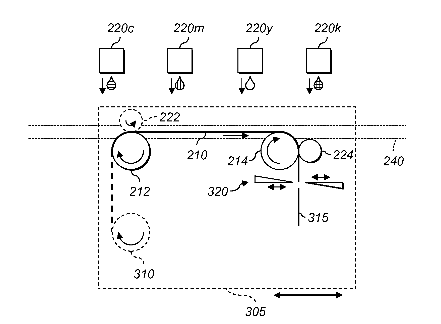
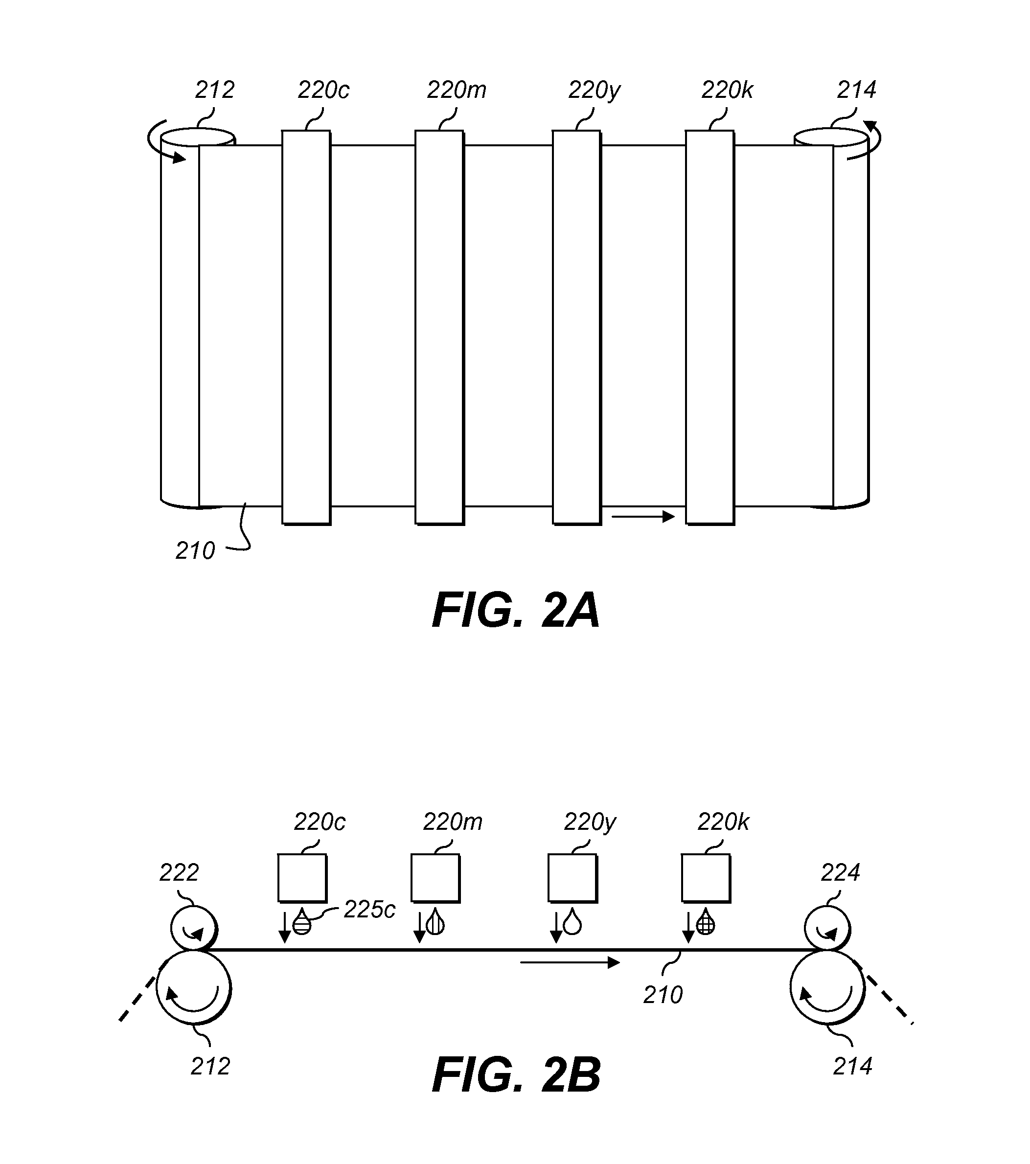
A multi-channel image is printed on a web receiver by a plurality of printing modules. The receiver is entrained around a take-up roll on a movable transport. During printing, the transport moves past the printing modules while the take-up roll holds the receiver in position with respect to the transport, and then the transport comes to a stop and the take-up roll draws the receiver across the transport. A cutter downstream of the take-up roll cuts off the printed portion of the web receiver to provide a printed sheet.

Description

FIELD OF THE INVENTION[0001]This invention relates to printing images on continuous-web receivers.BACKGROUND OF THE INVENTION[0002]Color and other multi-channel images can be printed using ink jet printers, multicolor transferable toner printers, heat sensitive coated paper printers, thermal dye transfer printers, and other types of printers. Many mass-market retail establishments have user-friendly kiosks at which shoppers make color prints. Because the kiosks use large amounts of paper, the images can be printed on a continuous web of paper, often supplied in roll form and fed from a feed roll to the printhead that applies the image to the receiver. The images are later separated from each other and from the web by a suitable cutter or knife.[0003]It is desirable when roll-feeding to pull the web past the printhead. This provides positive control of the web as it passes the printhead. In various schemes, the printhead forms part of the pulling apparatus, as in U.S. Pat. No. 5,441,...

Claims


Application Information

Patent Timeline
Patent Type & Authority Patents(United States)
IPC IPC(8): G03G9/08G01D15/24B41J2/175B41J11/00G01D15/10B41J2/325B41J17/00B41J2/435B41J2/01G01D11/00B41J29/38B41J2/385B41J2/315B41M5/00
CPCB41J3/543B41J15/165
Inventor LAWTHER, JOEL SHERWOODCORNELL, DAVID JAMES
Owner EASTMAN KODAK CO
Learn More