
Electric power steering device

a technology of electric power steering and steering wheel, which is applied in the direction of non-deflectable wheel steering, position/direction control, vehicle position/course/altitude control, etc., can solve the problems of large memory capacity, difficult to apply the technologies disclosed in both patent literatures, and variation of power-source voltage out of consideration. , to achieve good torque control, simple arithmetic process

Inactive Publication Date: 2013-12-10
HONDA MOTOR CO LTD
View PDF32 Cites 3 Cited by
  • Summary
  • Abstract
  • Description
  • Claims
  • Application Information

AI Technical Summary

Benefits of technology

The patent is about a way to control a motor that uses a nonlinear torque-current characteristic. The invention allows for good torque control by calculating the effective value and phase of motor current, and optimizing them to perform the torque control. This results in a simpler and more efficient way to control the motor. Overall, the invention provides an effective electric power steering device that works well with nonlinear motors.

Problems solved by technology

However, in the case of prior arts, conditions for obtaining the target current and the current advance angle are complicated, so that an arithmetic process time for controlling the torque of the synchronous reluctance motor becomes long, a processing capability of a CPU necessary for the arithmetic process and a memory capacity become large.
Also, in the synchronous reluctance motor, the largeness of a torque and the revolutionary speed of the torque which can be output varies depending on the state of a power-source voltage, however, the technologies disclosed in both patent literatures 1 and 2 leave the variation of a power-source voltage out of consideration.
Therefore, it is difficult to apply the technologies disclosed in both patent literatures 1 and 2 to the electric power steering device that uses a battery voltage because those technologies.

Method used


Image

  • Electric power steering device
  • Electric power steering device
  • Electric power steering device

Examples


Embodiment Construction

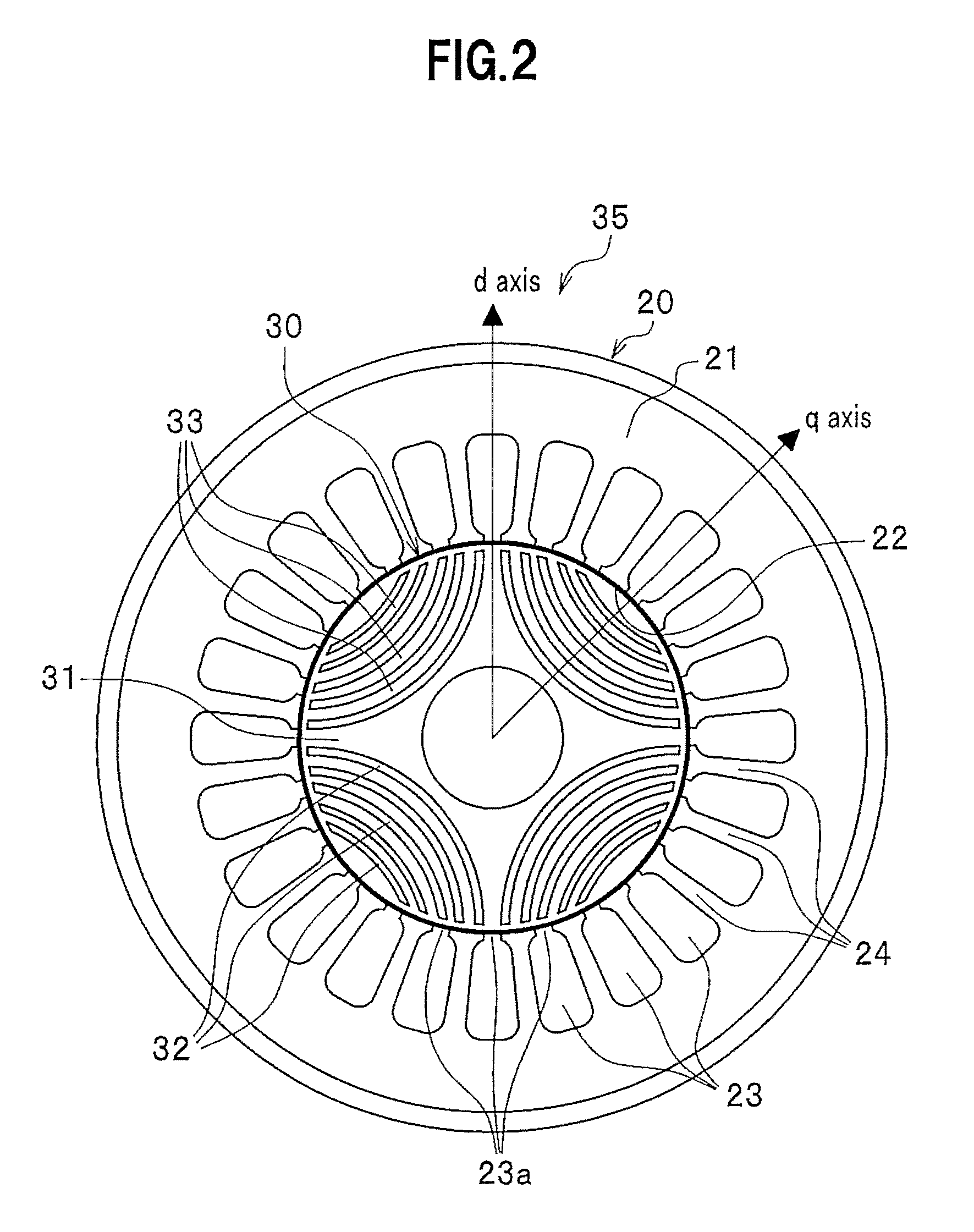
[0028]An embodiment of a electric power steering device using a synchronous reluctance motor according to the present invention will be explained below in detail with reference to the accompanying drawings.

[0029]1>

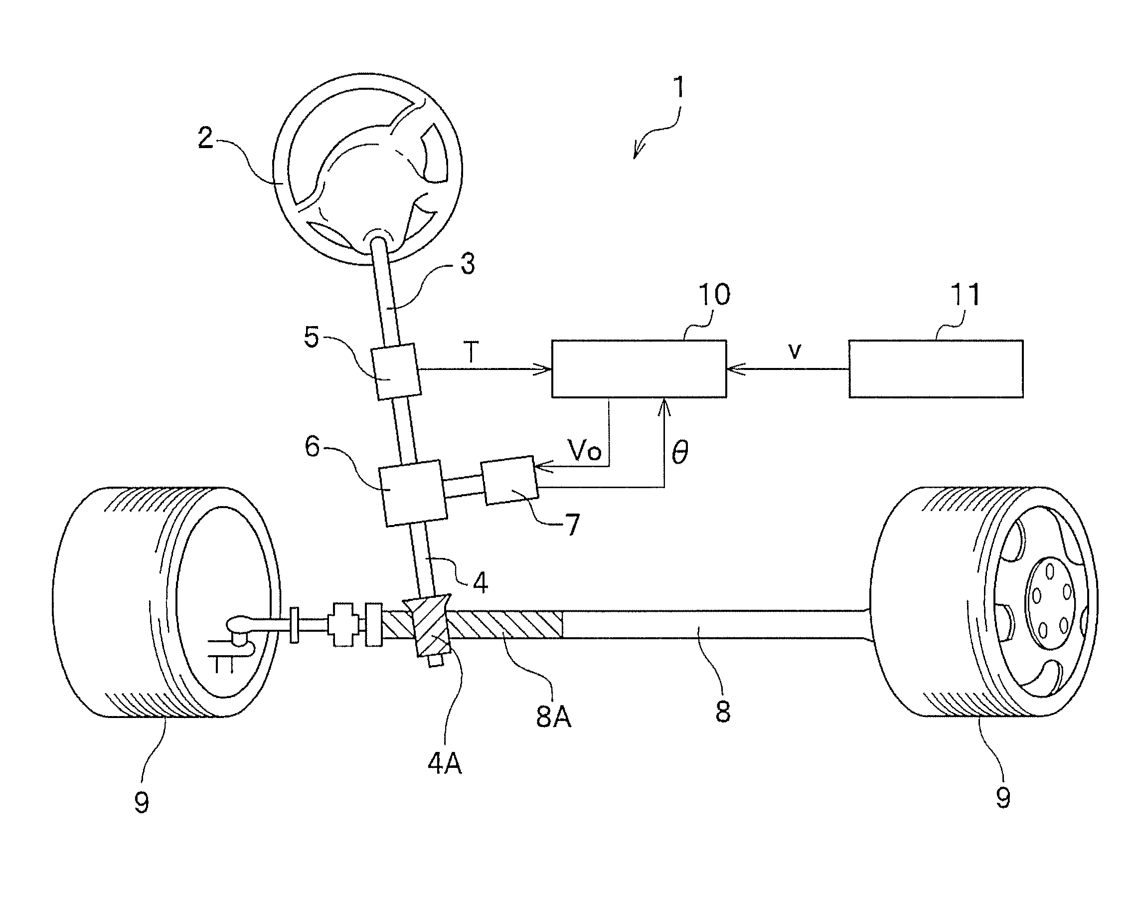
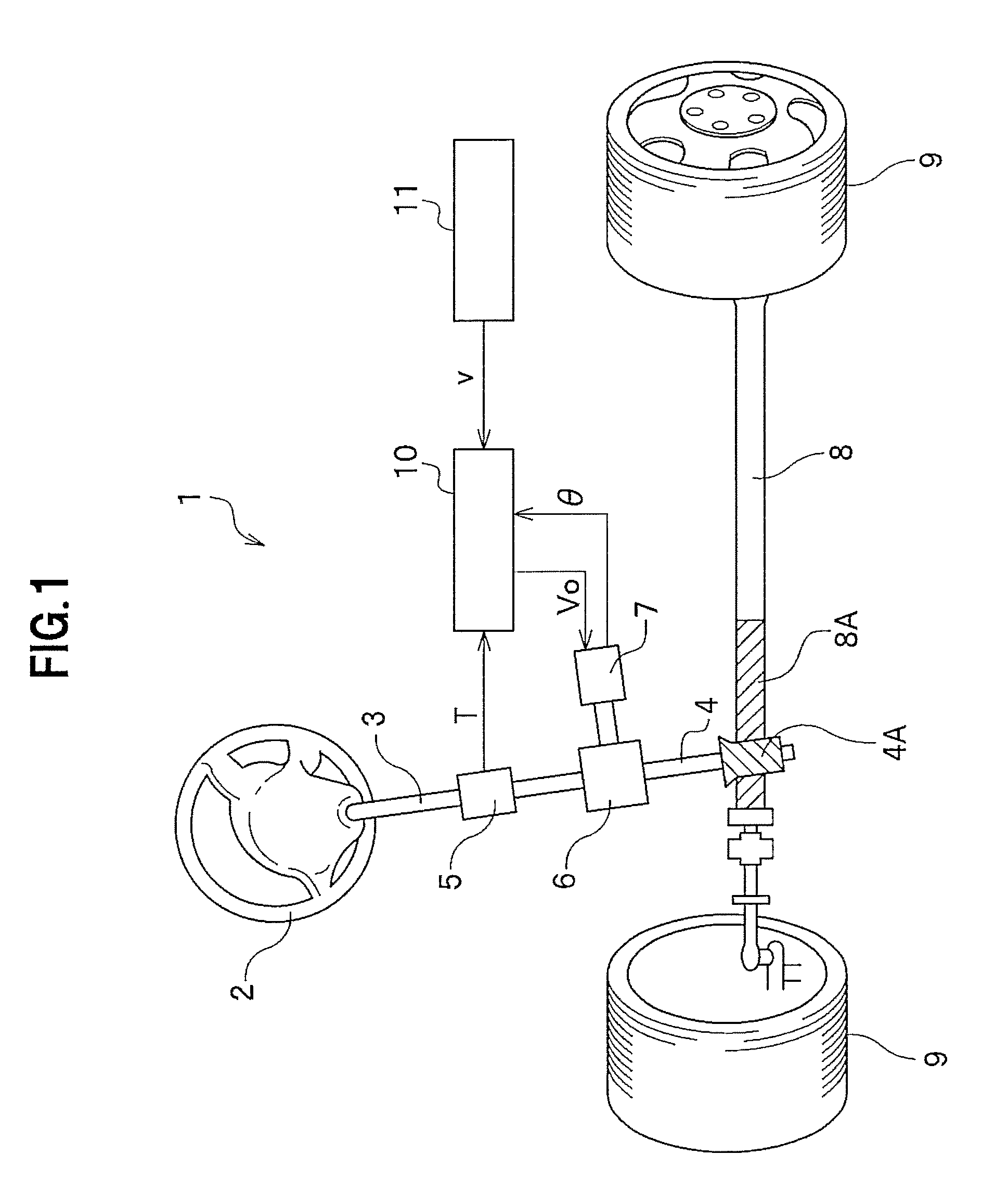
[0030]FIG. 1 is an overall configuration diagram of a electric power steering device 1 including a synchronous reluctance motor according to an embodiment of the present invention.

[0031]As shown in FIG. 1, the electric power steering device 1 includes a steering wheel 2, and the steering wheel 2 is joined with a pinion shaft 4 through a steering shaft 3. A steering torque generated by the operation of the steering wheel 2 given by a driver is transmitted to the pinion shaft 4 through the steering shaft 3. The pinion shaft 4 is provided with a magnetostrictive torque sensor 5 which detects the steering torque that acts on a steering system and a torque transmitting unit 6, and the torque transmitting unit 6 is coupled to an electric machinery (electric motor) 7 that applies...


PUM


Abstract

There is provided a electric power steering device which can perform torque control through a simple arithmetic process using a synchronous reluctance motor having a nonlinear current / torque characteristic. A target torque is transmitted from an EPS control unit 41 to a motor control unit 51. The motor control unit 51 calculates a target-current effective value I and a target-current phase θ from the input target torque. Based on the calculated target-current effective value I and target-current phase θ, calculation is changed whether to perform calculation so that the maximum torque (the maximum torque obtainable at the minimum current effective value) can be obtained, or to perform calculation so that the maximum output (the maximum output obtainable at the minimum current effective value) can be obtained in accordance with a duty ratio of an output by a PWM converting unit 57 comprising a three-phase inverter. Next, a three-phase biaxial converting unit 53 calculates a target q-axis current Iq and a target d-axis current Id from the target-current effective value I and the target-current phase θ, and the PWM converting unit 57 performs duty control in order to control the torque of a motor 58.

Description

BACKGROUND OF THE INVENTION[0001]1. Field of the Invention[0002]The present invention relates to a electric power steering device which controls a motor torque on the basis of a steering-torque signal and a speed signal in order to assist a steering, and more particularly, relates to the electric power steering device which assists a steering with a synchronous reluctance motor.[0003]2. Description of the Related Art[0004]A electric power steering device is a steering-force supporting device to reduce a steering force generated by a steering operation by a driver by causing an electric motor (a motor) to generate an auxiliary torque in accordance with the largeness of a steering torque of a vehicle and to transmit the auxiliary torque to a steering system. An example of such a motor used in the electric power steering device is a synchronous reluctance motor. The synchronous reluctance motor makes a rotary operation by a reluctance torque generated at a steel-plate layer of a rotato...

Claims


Application Information

Patent Timeline
Patent Type & Authority Patents(United States)
IPC IPC(8): B62D5/04B62D6/00B62D101/00B62D119/00H02P21/00H02P23/30H02P27/04H02P27/08
CPCB62D5/046H02P21/0089H02P21/06H02P25/021H02P25/024
Inventor NAKANO, YASUHIRO
Owner HONDA MOTOR CO LTD
Learn More