
Glass ceramic composition and glass ceramic substrate

a technology of glass ceramics and compositions, applied in ceramics, natural mineral layered products, solid-state devices, etc., can solve the problems of inferior chemical low relative permittivity of sintered bodies, and poor resistance of glass ceramic compositions to plating solutions, etc., to achieve stable temperature characteristics, low relative permittivity, and high electrical insulation reliability

Active Publication Date: 2013-11-26
MURATA MFG CO LTD
View PDF35 Cites 3 Cited by
  • Summary
  • Abstract
  • Description
  • Claims
  • Application Information

AI Technical Summary

Benefits of technology

The present invention is about a glass ceramic composition that can be fired at a low temperature of 1000° C or lower. The resulting glass ceramic sintered body has a low relative permittivity and stable temperature characteristic, as well as excellent electric insulation reliability, high Q value, and resistance to plating solution. The addition of a fourth ceramic containing zirconium oxide or manganese oxide as the main constituent promotes the crystallization of the glass and improves the mechanical strength of the substrate. The glass ceramic composition contains little barium and has improved electric insulation reliability when containing calcium oxide or strontium oxide as an additive constituent. It also allows for the use of copper or silver as the main constituent of the wiring conductors. Overall, this patent text presents a novel glass ceramic composition with improved properties suitable for high-frequency applications.

Problems solved by technology

However, the glass ceramic composition described in Patent Document 1 has a problem in that the Q value of a sintered body thereof is relatively low and the glass ceramic composition is inferior in chemical resistance, such as plating solution resistance.
However, there is a relatively large gap between the thermal expansion coefficient of the sintered body of the glass ceramic composition described in Patent Document 1 and the thermal expansion coefficient of the sintered body of the glass ceramic composition described in Patent Document 2, and there is a possibility that defects such as peeling, cracks and pores may be developed in the laminate ceramic substrate.Patent Document 1: Japanese Unexamined Patent Publication No. 2008-37739Patent Document 2: International Publication WO 2008 / 018408

Method used

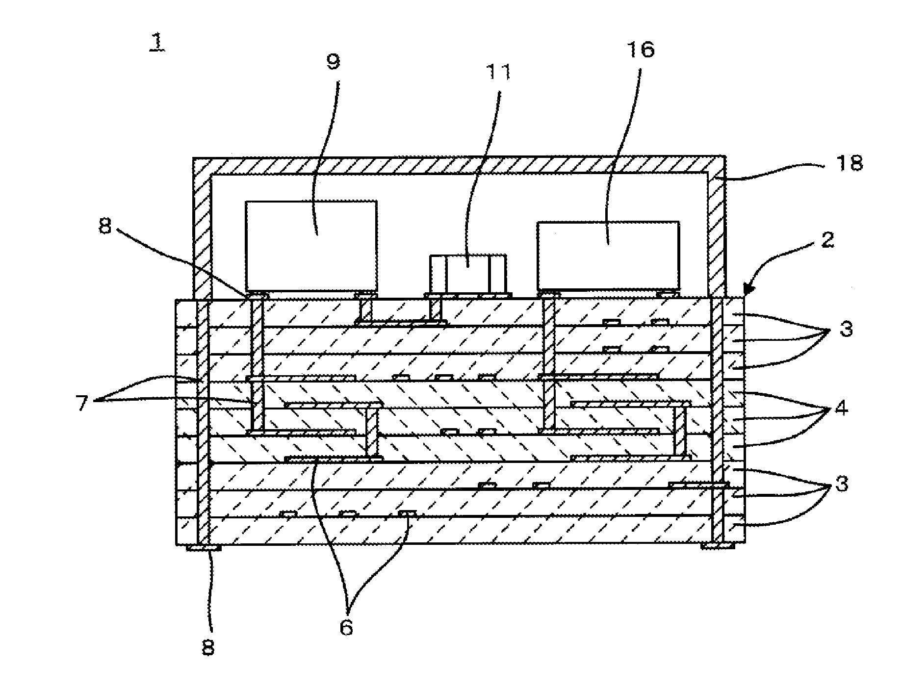
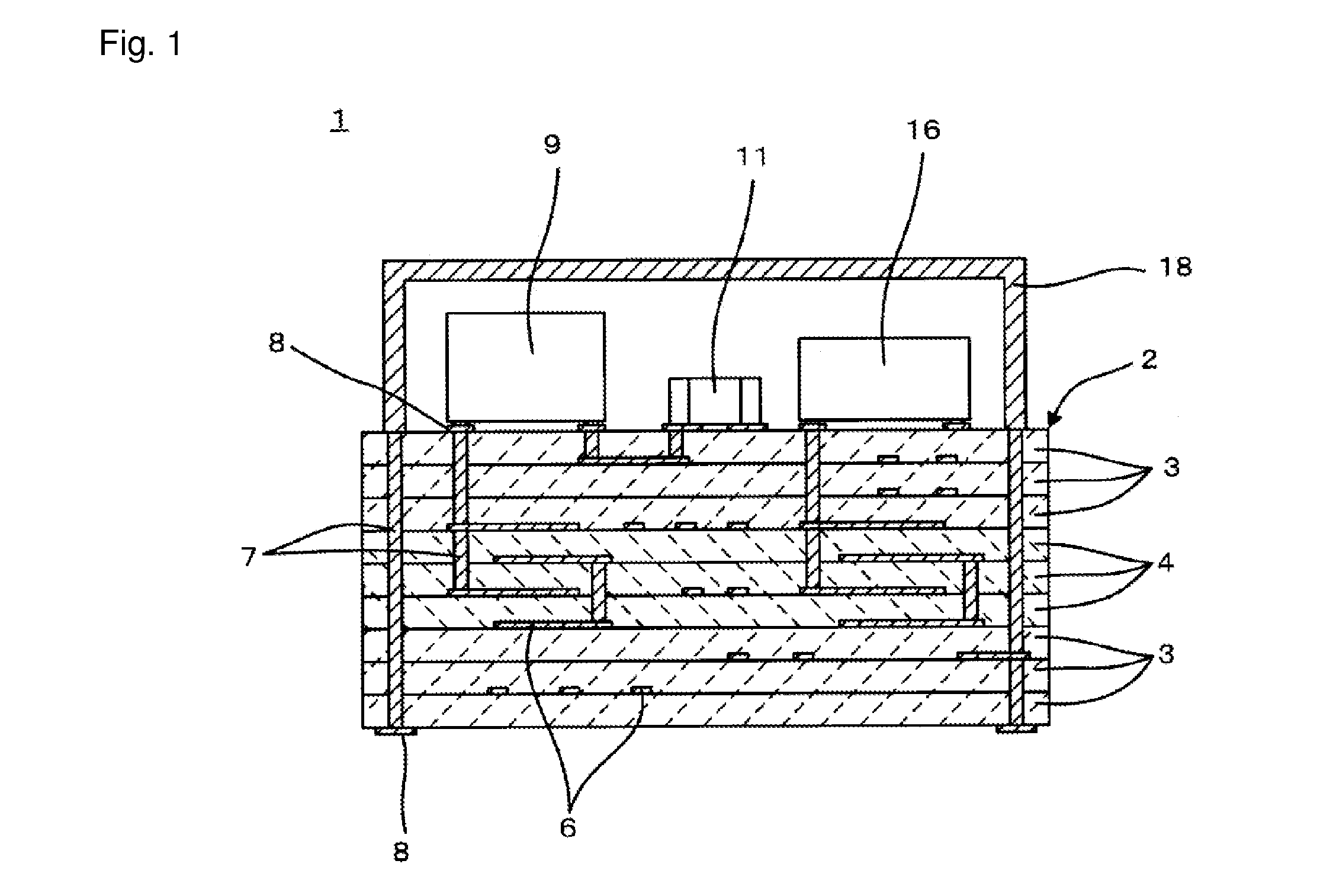
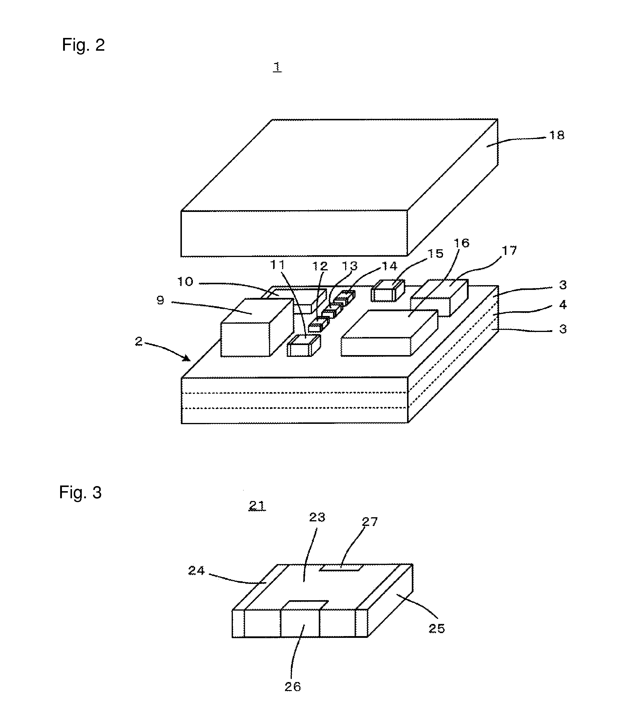

Image

  • Glass ceramic composition and glass ceramic substrate
  • Glass ceramic composition and glass ceramic substrate
  • Glass ceramic composition and glass ceramic substrate

Examples


experiment example 1

[0143]First, borosilicate glasses with various compositions shown in Table 1 were prepared for use as a borosilicate glass contained in the glass ceramic composition.

[0144]

TABLE 1GlassLi2OMgOCaOSrOB2O3SiO2ZnOsymbol(Wt %)(Wt %)(Wt %)(Wt %)(Wt %)(Wt %)(Wt %)NoteG1*230.501520257.5G2329.501520257.5G3152501017.5257.5G4*162401017.5257.5G5*517.502025257.5G6520017.525257.5G75500517.5157.5G85505017.5157.5G95503217.5157.5G10*552.502.517.5157.5Devitrifi-cationG11*533.501514257.5Devitrifi-cationG12532.501515257.5G13527.501030207.5G14*526.501031207.5G15*543.50152097.5Devitrifi-cationG16542.501520107.5G1752501017.5357.5G18*52401017.5367.5G19*53001520255G2052901520256G21527.50517.52520G22*526.50517.52521G23*526.516020257.5G24527.515020257.5G255252.51520257.5G26*521.502620207.5G2752002517.5257.5G28530102.520257.5G29527.501520257.5

[0145]In Table 1, those “glass symbol” marked with an asterisk indicates a glass having the composition out of the scope of the present invention.

[0146]The glasses shown i...

experiment example 2

[0176]This Experiment Example 2 is characterized by using manganese oxide in place of zirconium oxide used in Experiment Example 1 as the fourth ceramic.

[0177]First, the borosilicate glasses shown in Table 1 were used as the borosilicate glass contained in the glass ceramic composition.

[0178]A Mg2SiO4 powder having an average grain diameter (median grain diameter D50) of 0.8 μm was prepared as a first ceramic for the glass ceramic composition, a SrTiO3 powder having an average grain diameter of 1.5 μm and a TiO2 powder having an average grain diameter of 1.0 μm were respectively prepared as a second ceramic, a BaZrO3 powder having an average grain diameter of 1.0 μm was prepared as a third ceramic, and a MnO powder having an average grain diameter of 1.0 μm was prepared as a fourth ceramic.

[0179]In order to obtain a glass ceramic composition of each of the samples shown in Table 4, the first ceramic, the borosilicate glass, the second ceramic, the third ceramic and the fourth cerami...

experiment example 3

[0200]This Experiment Example 3 is characterized by using both of zirconium oxide used in Experiment Example 1 and manganese oxide used in Experiment Example 2 as the fourth ceramic.

[0201]First, the borosilicate glasses shown in Table 1 were used as the borosilicate glass contained in the glass ceramic composition.

[0202]A Mg2SiO4 powder having an average grain diameter (median grain diameter D50) of 0.8 μm was prepared as a first ceramic contained in the glass ceramic composition, a SrTiO3 powder having an average grain diameter of 1.5 μm and a TiO2 powder having an average grain diameter of 1.0 μm were respectively prepared as a second ceramic, a BaZrO3 powder having an average grain diameter of 1.0 μm was prepared as a third ceramic, and a ZrO2 powder having an average grain diameter of 1.0 μm and a MnO powder having an average grain diameter of 1.0 μm were prepared as a fourth ceramic.

[0203]Next, the first ceramic, the borosilicate glass, the second ceramic, the third ceramic and...


PUM


Abstract

Provided is a glass ceramic composition which can be fired at a temperature of 1000° C. or lower, and a sintered body of which has a low relative permittivity and a high Q value, stable temperature characteristic and high reliability, and is excellent in plating solution resistance. The glass ceramic composition provides a low dielectric constant layer for inclusion in a laminate glass ceramic substrate in a ceramic multilayer module. It includes a first ceramic having forsterite as the main constituent, a second ceramic having at least one of SrTiO3 and TiO2 as the main constituent, a third ceramic having BaZrO3 as the main constituent, a fourth ceramic having at least one of ZrO2 and MnO as the main constituent, and 3 weight % or more of a borosilicate glass containing Li2O, MgO, B2O3, SiO2 and ZnO, which further contains an additive constituent including at least one of CaO and SrO.

Description

[0001]This is a continuation of application Serial No. PCT / JP2009 / 068799, filed Nov. 4, 2009, the content of which are incorporated herein by reference.TECHNICAL FIELD[0002]The present invention relates to a glass ceramic composition including a glass constituent so as to enable firing at low temperature, and a glass ceramic substrate configured by use of the same.BACKGROUND ART[0003]As one effective way for enabling miniaturization of electronic devices, multifunctional electronic components are used in electronic devices. Examples of the multifunctional electronic components include ceramic multilayer modules.[0004]The ceramic multilayer module includes a laminate ceramic substrate. Wiring conductors, which are for performing the function of electrical connection or for configuring passive elements such as a capacitor and an inductor, are incorporated in the laminate ceramic substrate, and various electronic components are mounted on the laminate ceramic substrate.[0005]In this wa...

Claims


Application Information

Patent Timeline
Patent Type & Authority Patents(United States)
IPC IPC(8): B32B15/04C03C6/00B32B17/00
CPCC04B35/20H01B3/12H05K1/0306H05K3/4611H05K3/4629H01L2224/16227H01L2924/15192H01L2924/15313H01L2924/16251H01L2924/19105Y10T428/24942
Inventor ADACHI, HIROSHIGESAKAMOTO, SADAAKI
Owner MURATA MFG CO LTD
Learn More