
Modular multi-level power converter with second and third order harmonics reduction filter

a multi-level, harmonic reduction technology, applied in power conversion systems, conversion with reversal, electrical equipment, etc., can solve problems such as system instability, inability to avoid distinctive harmonics, and increase losses, and achieve the effect of reducing the main disturbing component of the circulating curren

Active Publication Date: 2013-10-22
HITACHI ENERGY SWITZERLAND AG
View PDF23 Cites 2 Cited by
  • Summary
  • Abstract
  • Description
  • Claims
  • Application Information

AI Technical Summary

Benefits of technology

The patent introduces a device that helps reduce harmonics in a power system. This device, called a passive electronic filter, blocks out the harmonics that cause the most problems in the system. This improves the performance of the control unit that manages the power semiconductor switches. By reducing the need for high-rated switches, the device saves money and makes the system more reliable. The filter reduces harmonics at two and three times the frequency of the AC voltage. This helps remove one type of harmonic without needing a transformer.

Problems solved by technology

What the inventors realized is that at each switching event in the power electronic switches of the converter, harmonics appear in the circulating current causing increased losses.
As a worst case, some of the harmonics with distinctively high amplitude in the circulating currents could even lead to system instability.
The introduction of additional inductors, as described in WO 2008 / 067785, helps to obtain a general current limitation in the converter circuit but does nothing to avoid the distinctive harmonics as such.

Method used


Image

  • Modular multi-level power converter with second and third order harmonics reduction filter
  • Modular multi-level power converter with second and third order harmonics reduction filter
  • Modular multi-level power converter with second and third order harmonics reduction filter

Examples


Embodiment Construction

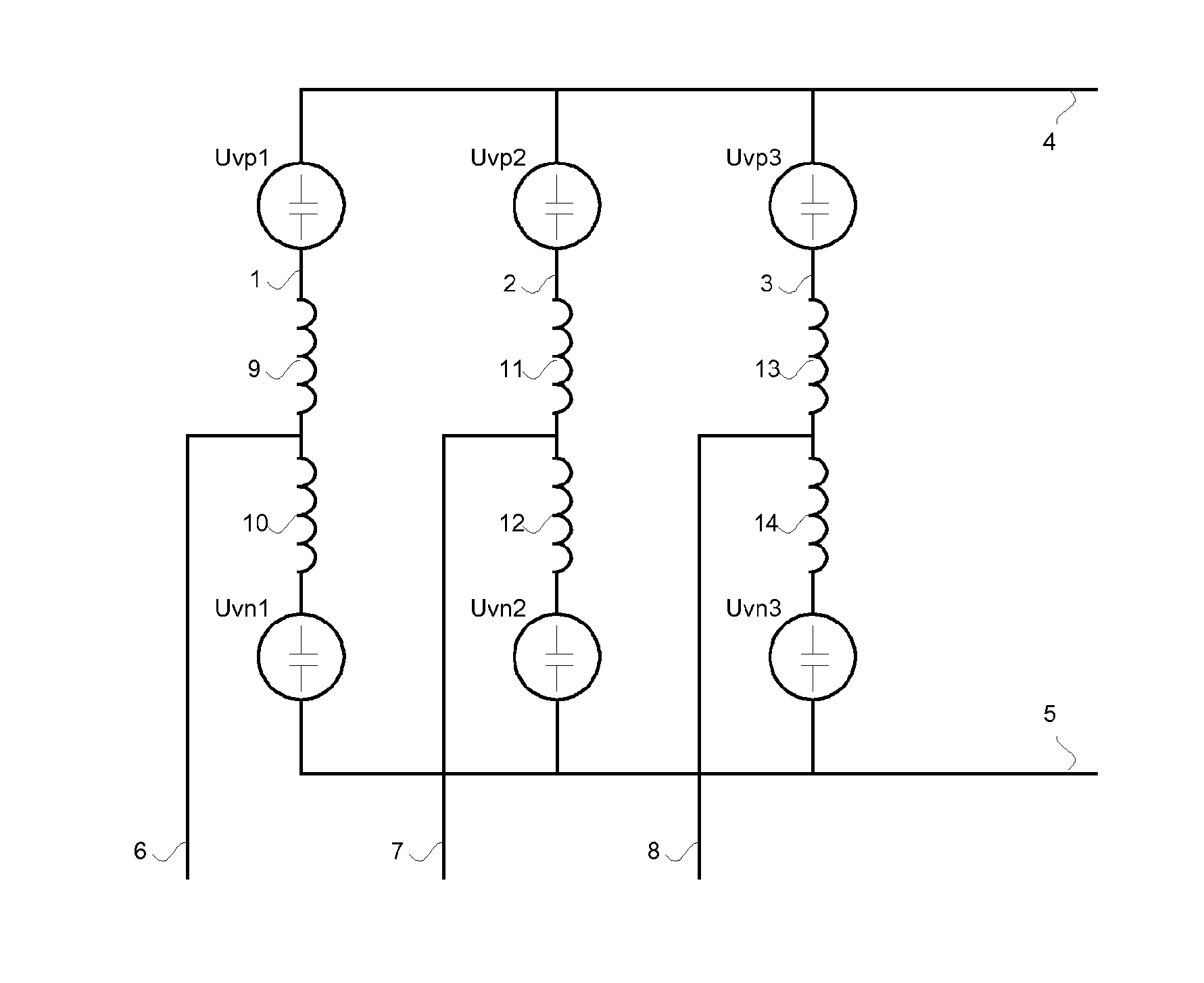
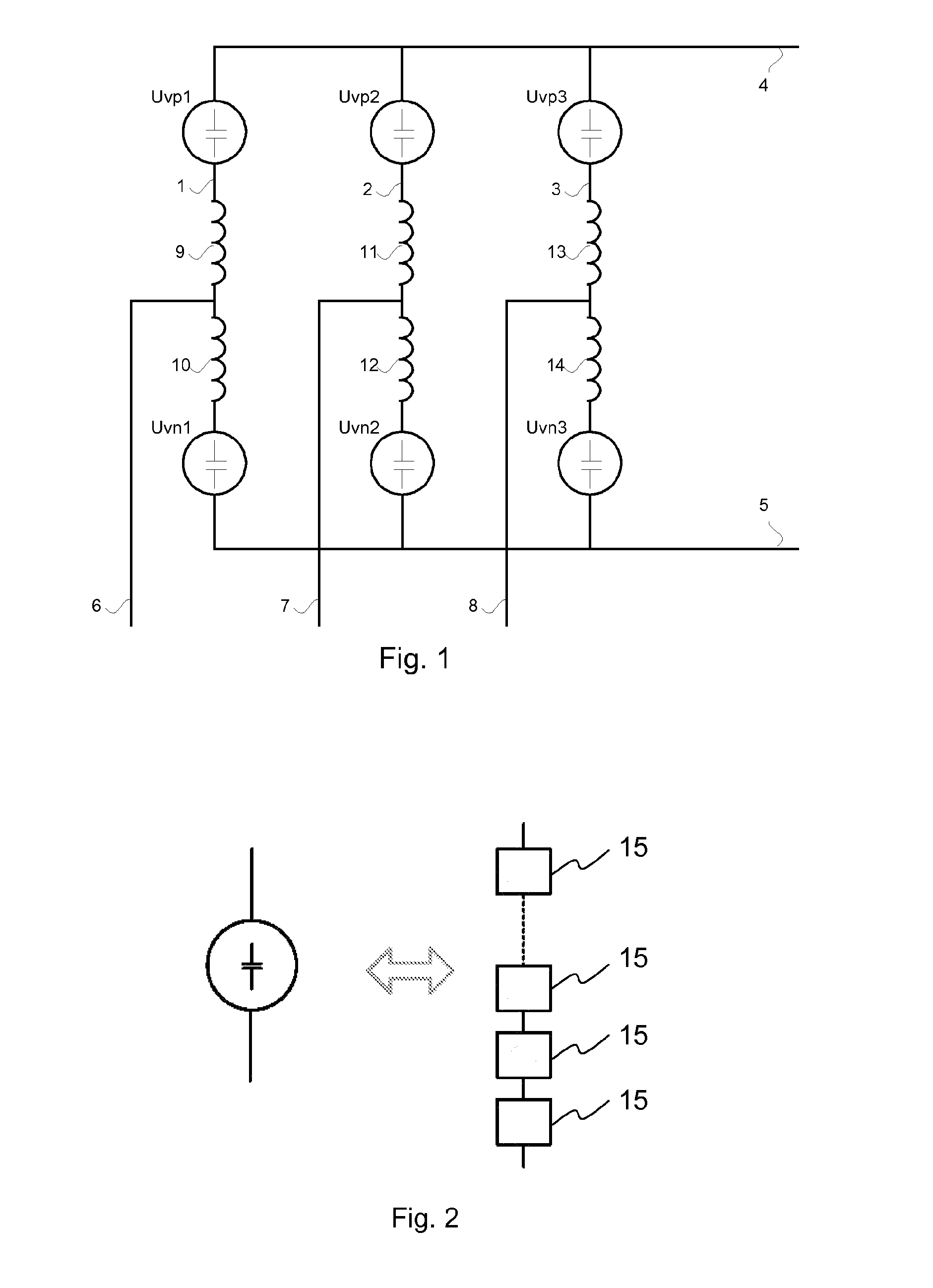
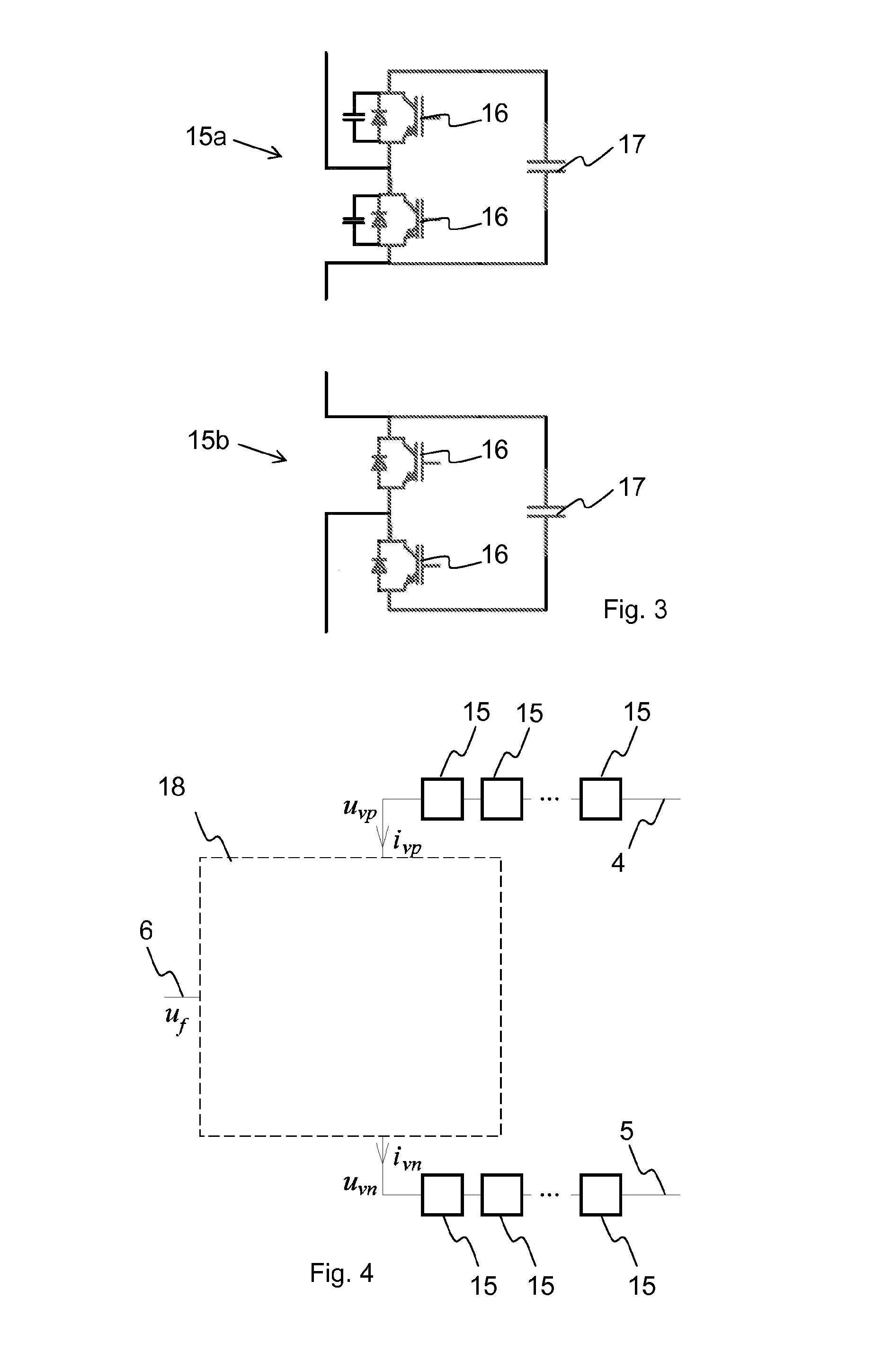
[0030]The device for converting a DC voltage into an AC voltage and vice versa according to the invention can contain either a single phase leg or multiple phase legs, depending on how many phases the AC voltage has. FIG. 1 shows a three-phase converter known in the art. The three phase legs 1, 2 and 3 of the device of FIG. 1 each comprise two so-called arms in series-connection: a positive, upper arm which is connected to a first DC terminal 4 at a positive voltage level, and a negative, lower arm, which is connected to a second DC terminal 5 at zero or a negative voltage level. Each positive arm comprises a series-connection of an upper voltage source Uvpi and a first passive energy storage element, here in the form of an inductor 9, 11 or 13, respectively, and each negative arm comprises a second passive energy storage element, here also in the form of an inductor 10, 12 or 14, respectively, and a lower voltage source Uvni, where i stands for the number of the corresponding phase...


PUM


Abstract

A device for converting a DC voltage into an AC voltage includes a passive electronic filter having a first and second energy storage element, a third energy storage element placed between the first and second energy storage elements, a fourth energy storage element connected between a junction of the first energy storage element and the third energy storage element and an AC terminal and a fifth energy storage element connected between a junction of the second energy storage element and the third energy storage element and the AC terminal. The energy storage elements are of two different types, capacitive and inductive, with values selected to provide reduction of frequency components at two times the fundamental frequency of the AC voltage and at three times the fundamental frequency of the AC voltage.

Description

FIELD OF THE INVENTION[0001]The invention is related to a power converter with multi-level voltage output in the form of a device for converting a DC voltage into an AC voltage and vice versa comprising at least one phase leg with a first voltage source and a first passive energy storage element connected in series between a first DC terminal and a first AC terminal and with a second passive energy storage element and a second voltage source connected in series between the first AC terminal and a second DC terminal, where each of the voltage sources comprises at least a first and a second submodule in series-connection, each submodule comprising at least one power electronic switch connected in parallel with at least one capacitor.BACKGROUND ART[0002]In the art, multi-level converters are known to be used in order to reduce harmonic distortion in the output of voltage source converters. A multilevel converter is a converter where the output voltage—or, in case of a multiphase conver...

Claims


Application Information

Patent Timeline
Patent Type & Authority Patents(United States)
IPC IPC(8): H02M7/79
CPCH02M1/126H02M1/14H02M7/49H02M2007/4835H02M7/4835
Inventor HARNEFORS, LENNARTNORRGA, STAFFANSHUKLA, ANSHUMAN
Owner HITACHI ENERGY SWITZERLAND AG
Learn More