
Etching radical controlled gas chopped deep reactive ion etching

a radical control and reactive ion technology, applied in the direction of electrical equipment, decorative surface effects, decorative arts, etc., can solve the problems of affecting device performance, affecting device performance, and requiring even more stringent requirements

Active Publication Date: 2013-10-01
RGT UNIV OF CALIFORNIA
View PDF7 Cites 7 Cited by
  • Summary
  • Abstract
  • Description
  • Claims
  • Application Information

AI Technical Summary

Benefits of technology

This method enables the production of smooth sidewalls with reduced roughness, allowing for the transfer of sub-50 nm features with high aspect ratios, improving the control of anisotropy and etching rates, and minimizing radiation damage, thereby enhancing the fabrication of nanostructures.

Problems solved by technology

These requirements become even more stringent when etching nanoresolution devices due to the extremely small dimensions involved.
Unfortunately, bombardment by energetic particles induces complications due to radiation damage, undercutting, and contamination.
34 (1995) 2107] can result in detrimental device performance.
These are very serious problems to overcome for manufacturing of future nano-scale devices (devices with characteristic dimensions typically measured in nm, or 10−9 m.
Unfortunately, this spontaneous Si+F reaction makes anisotropy control a very difficult issue.
Extending gas-chopping technology to the sub-50 nm regime is challenging.
Gas chopping typically results in a roughness, scalloping, or rippling of the sidewalls.
In the gas chopping technique, periodically changing the supply of deposition and etch precursors produces overall anisotropically etched trenches, however, the sidewall surfaces of etched features are typically rippled.
By increasing the gas-chopping frequency, the amplitude of the ripples are reduced to the 10 nm range, but this is still too large for sub-50 nm structures.
While increasing the chopping frequency still further is theoretically possible, in practice this cannot be achieved due to the relatively long residence times of gas precursors and products, coupled with limited pumping speeds.

Method used


Image

  • Etching radical controlled gas chopped deep reactive ion etching
  • Etching radical controlled gas chopped deep reactive ion etching
  • Etching radical controlled gas chopped deep reactive ion etching

Examples


Embodiment Construction

Defined Terms

[0036]Computer means any device capable of performing the steps developed in this invention to result in an optimal etching radical controlled gas chopped deep reactive ion etching process, including but not limited to: a microprocessor, a digital state machine, a field programmable gate array (FGPA), a digital signal processor, a collocated integrated memory system with microprocessor and analog or digital output device, a distributed memory system with microprocessor and analog or digital output device connected with digital or analog signal protocols.

[0037]Computer readable media means any source of organized information that may be processed by a computer to perform the steps developed in this invention to result in an optimal etching radical controlled gas chopped deep reactive ion etching process, but not limited to: a magnetically readable storage system; optically readable storage media such as punch cards or printed matter readable by direct methods or methods ...


PUM

PropertyMeasurementUnit
surface roughnessaaaaaaaaaa

Abstract

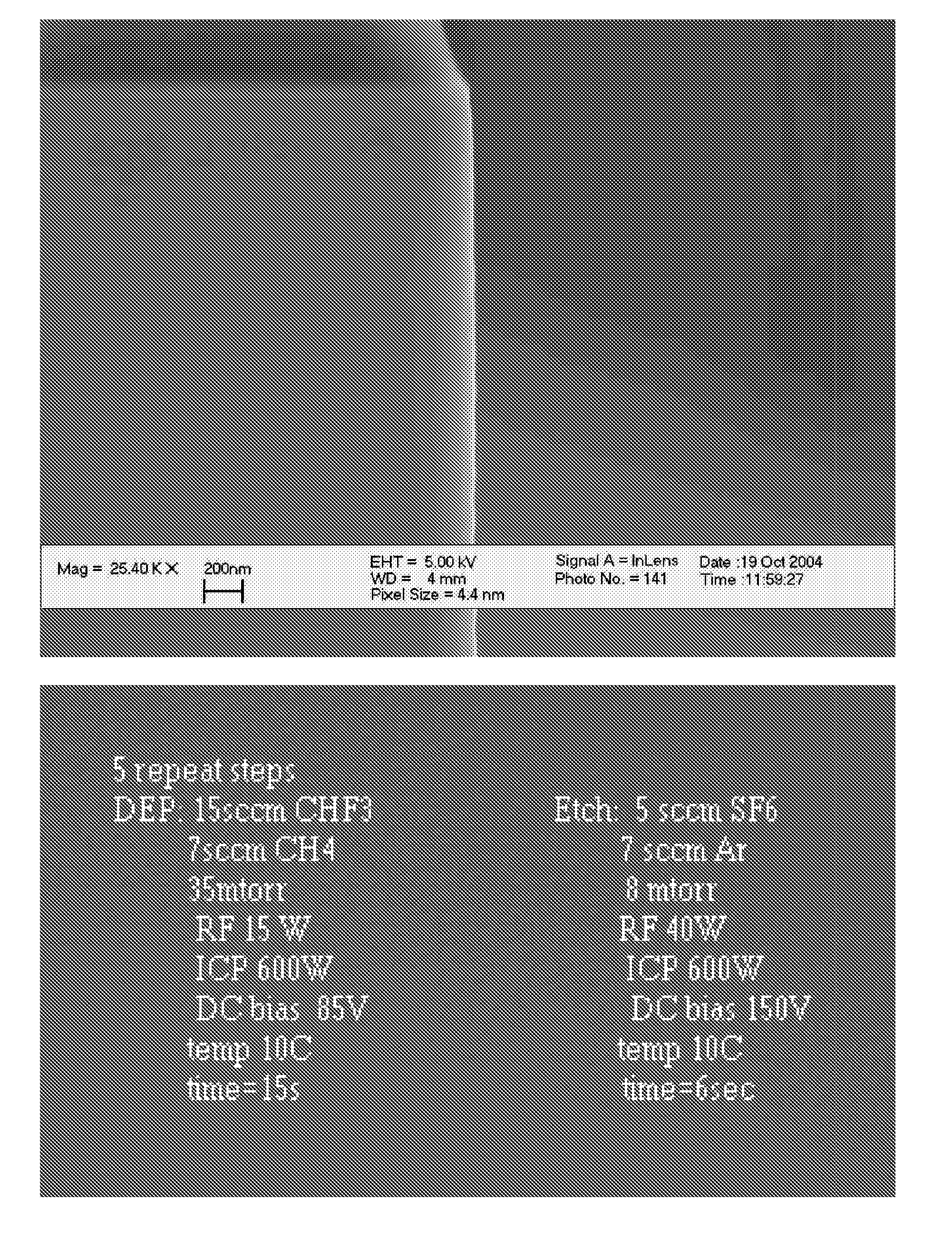
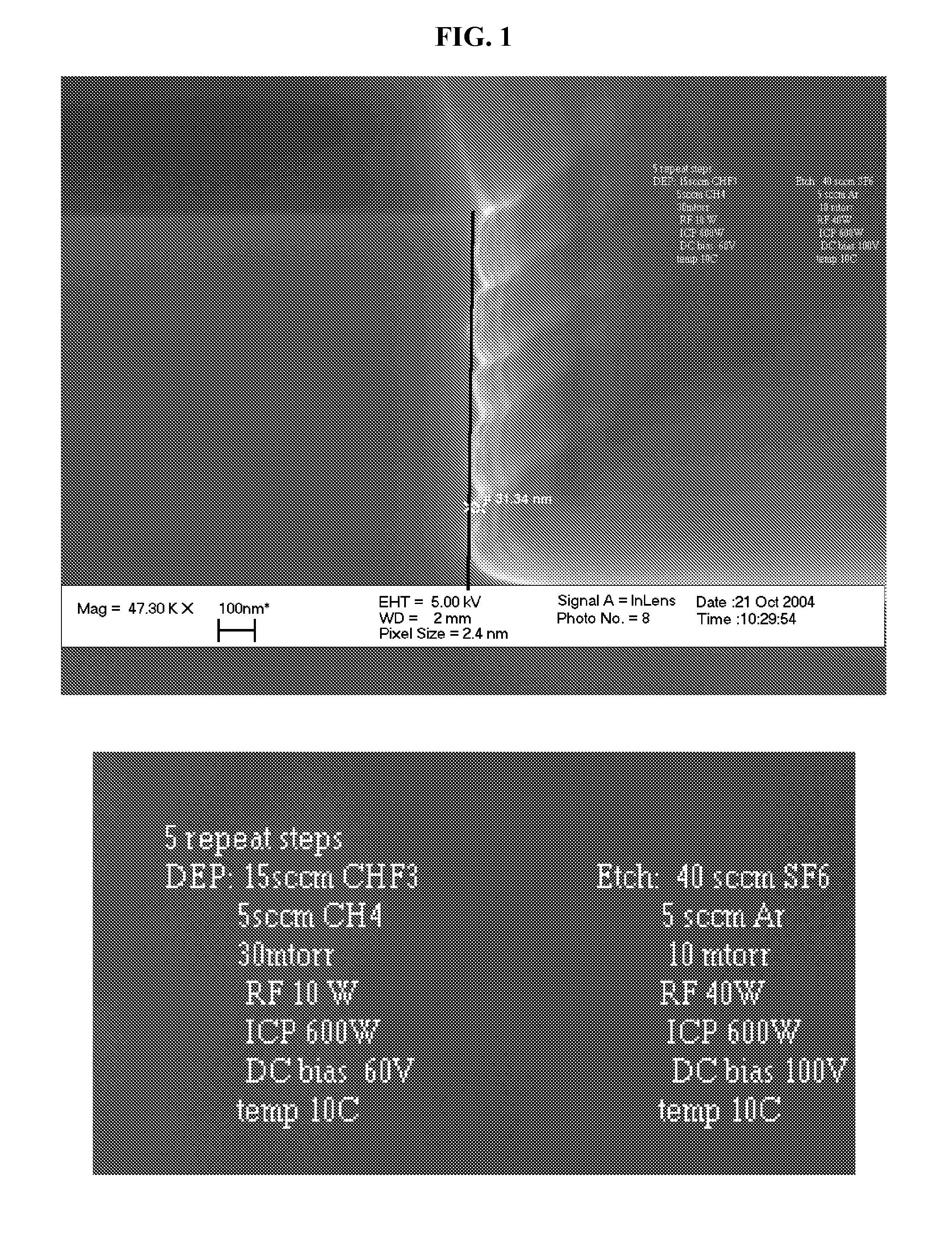
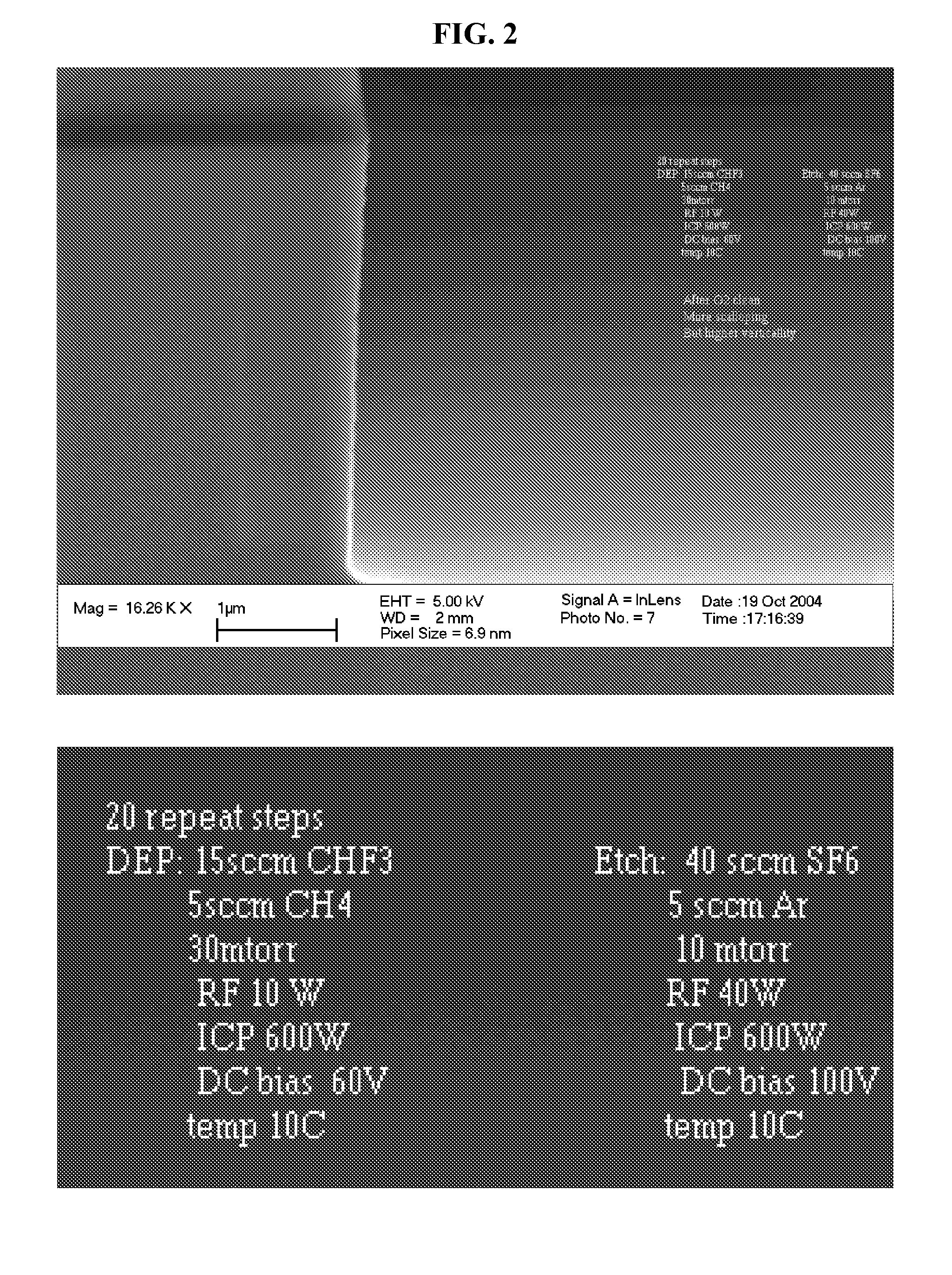
A method for silicon micromachining techniques based on high aspect ratio reactive ion etching with gas chopping has been developed capable of producing essentially scallop-free, smooth, sidewall surfaces. The method uses precisely controlled, alternated (or chopped) gas flow of the etching and deposition gas precursors to produce a controllable sidewall passivation capable of high anisotropy. The dynamic control of sidewall passivation is achieved by carefully controlling fluorine radical presence with moderator gasses, such as CH4 and controlling the passivation rate and stoichiometry using a CF2 source. In this manner, sidewall polymer deposition thicknesses are very well controlled, reducing sidewall ripples to very small levels. By combining inductively coupled plasmas with controlled fluorocarbon chemistry, good control of vertical structures with very low sidewall roughness may be produced. Results show silicon features with an aspect ratio of 20:1 for 10 nm features with applicability to nano-applications in the sub-50 nm regime. By comparison, previous traditional gas chopping techniques have produced rippled or scalloped sidewalls in a range of 50 to 100 nm roughness.

Description

CROSS REFERENCE TO RELATED APPLICATIONS[0001]This application claims benefit of priority to U.S. Provisional patent application 60 / 687,392, filed Jun. 2, 2005, which is hereby incorporated by reference in its entirety.STATEMENT REGARDING FEDERAL FUNDING[0002]This invention was made with U.S. Government support under Contract Number DE-AC02-05CH11231 between the U.S. Department of Energy and The Regents of the University of California for the management and operation of the Lawrence Berkeley National Laboratory. The U.S. Government has certain rights in this invention.REFERENCE TO A COMPUTER PROGRAM[0003]Not applicable.BACKGROUND OF THE INVENTION[0004]1. Field of the Invention[0005]The present invention pertains generally to methods used in lithographic etching, more specifically to high aspect ratio anisotropic etching with smooth etched sidewalls.[0006]2. Description of the Relevant Art[0007]Etching of Si surfaces using halogens plasmas is a central process in the microstructuring ...

Claims


Application Information

Patent Timeline
Patent Type & Authority Patents(United States)
IPC IPC(8): H01L21/302H01L21/461
CPCH01L21/30655
Inventor OLYNICK, DEIRDRERANGELOW, IVOCHAO, WEILUN
Owner RGT UNIV OF CALIFORNIA
Learn More