
Blind adaptive filter for narrowband interference cancellation

a narrowband interference and adaptive filter technology, applied in the direction of line-faulst/interference reduction, amplitude demodulation, pulse technique, etc., can solve the problems of signal synchronization failure, the frequency filter circuit in the electronic system which has been widely applied in communication systems is usually very complicated, and the transport performance of a wideband mobile communication system can be seriously degraded

Active Publication Date: 2013-08-13
MONTAGE TECHNOLOGY CO LTD
View PDF2 Cites 2 Cited by
  • Summary
  • Abstract
  • Description
  • Claims
  • Application Information

AI Technical Summary

Benefits of technology

The present invention provides a blind adaptive filter for narrowband interference cancellation that can be widely used. This means that the filter can be used in different situations and on different types of equipment. This makes it easier to develop and test the filter, which helps to improve its performance and reliability.

Problems solved by technology

The transport performance of a wideband mobile communication system can be seriously degraded by narrowband interferences from the same channel or from adjacent channels in both analog and digital systems.
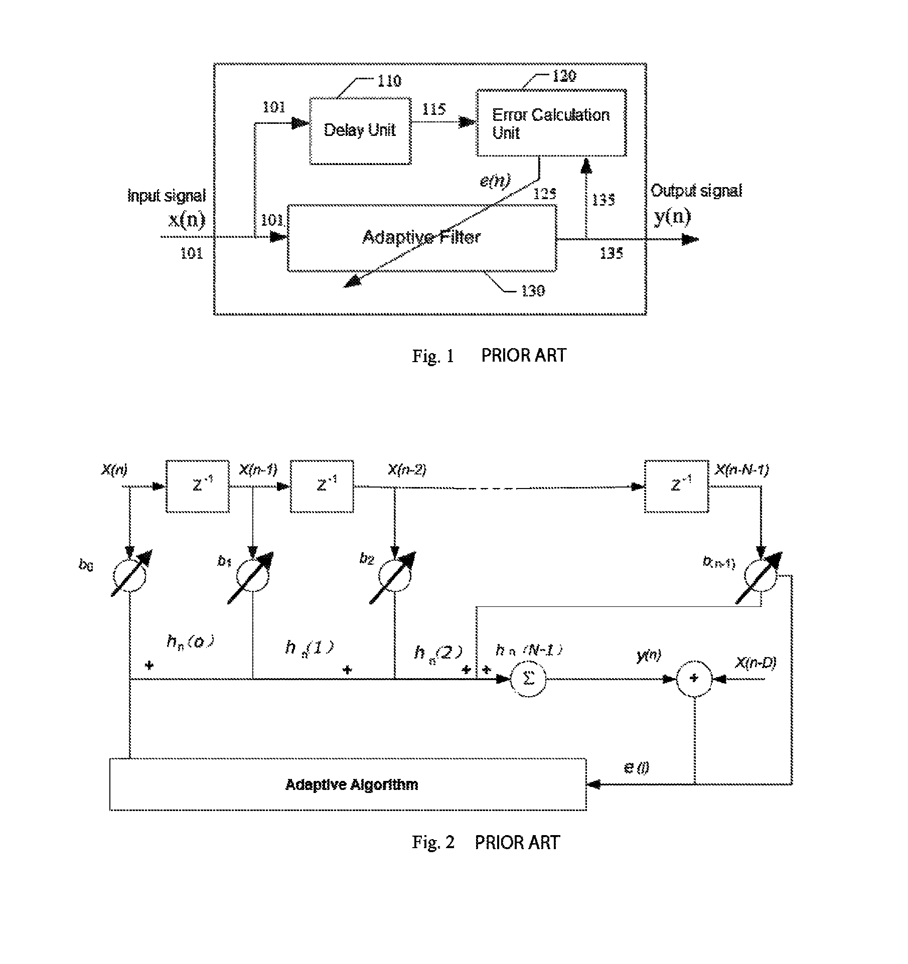
Frequency filter circuit in the electronic system which has been widely applied in communication systems is usually very complicated and the product performance is directly determined by the performance of filters.
Unfortunately, when interference increases beyond a critical level, signal synchronization fails.
However, this method has the least robustness in tracking the change of the interference, even when FFT is performed frequently.
However, the optimization convergence speed is very slow and only interference with a given spectral shape is removed.
Therefore, these techniques can not apply to more general situations, for example, in cases of frequency hopping or fast shifting centre frequency.

Method used


Image

  • Blind adaptive filter for narrowband interference cancellation
  • Blind adaptive filter for narrowband interference cancellation
  • Blind adaptive filter for narrowband interference cancellation

Examples


Embodiment Construction

[0033]The present invention is further explained in detail according to the accompanying drawings. It should be noted that figures are schematic representations of the embodiments, and not drawn to scale.

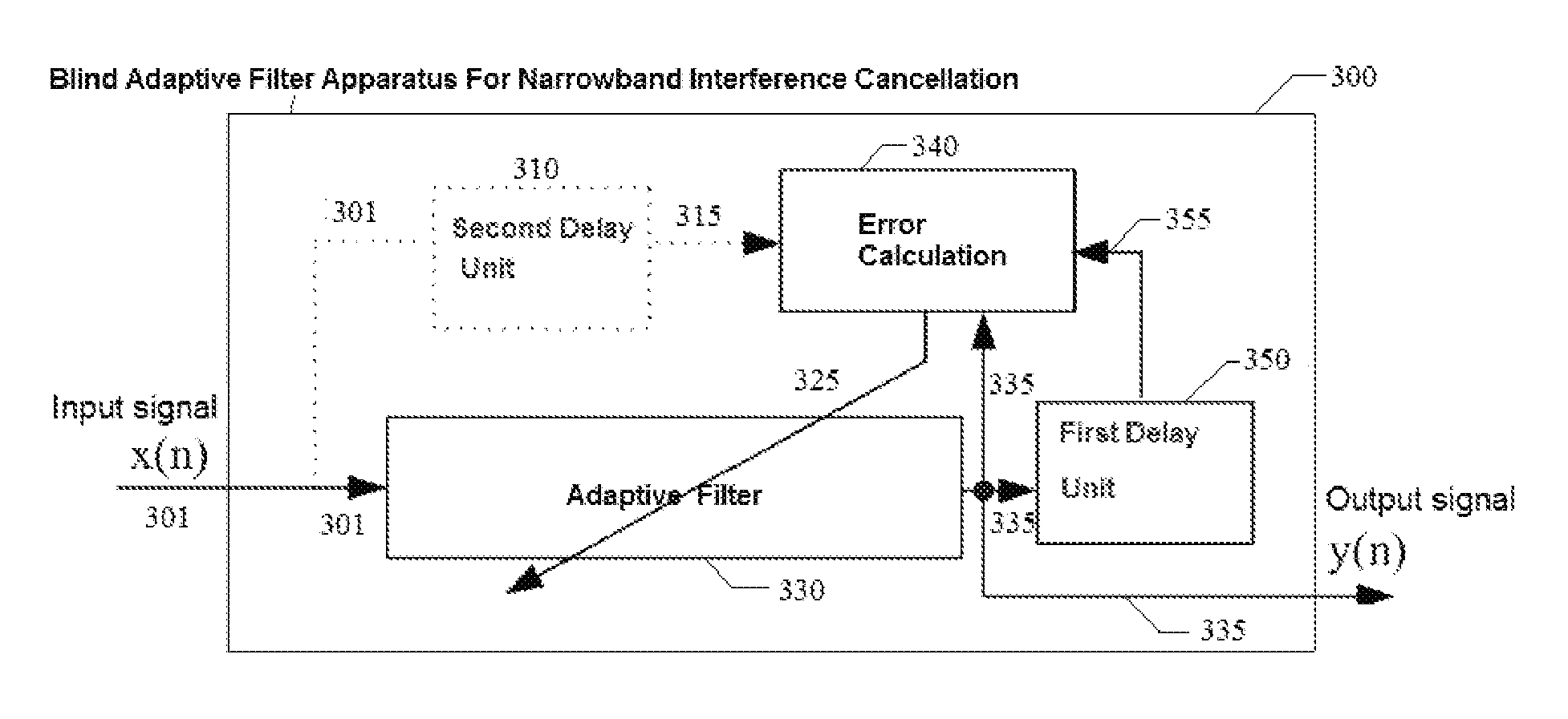
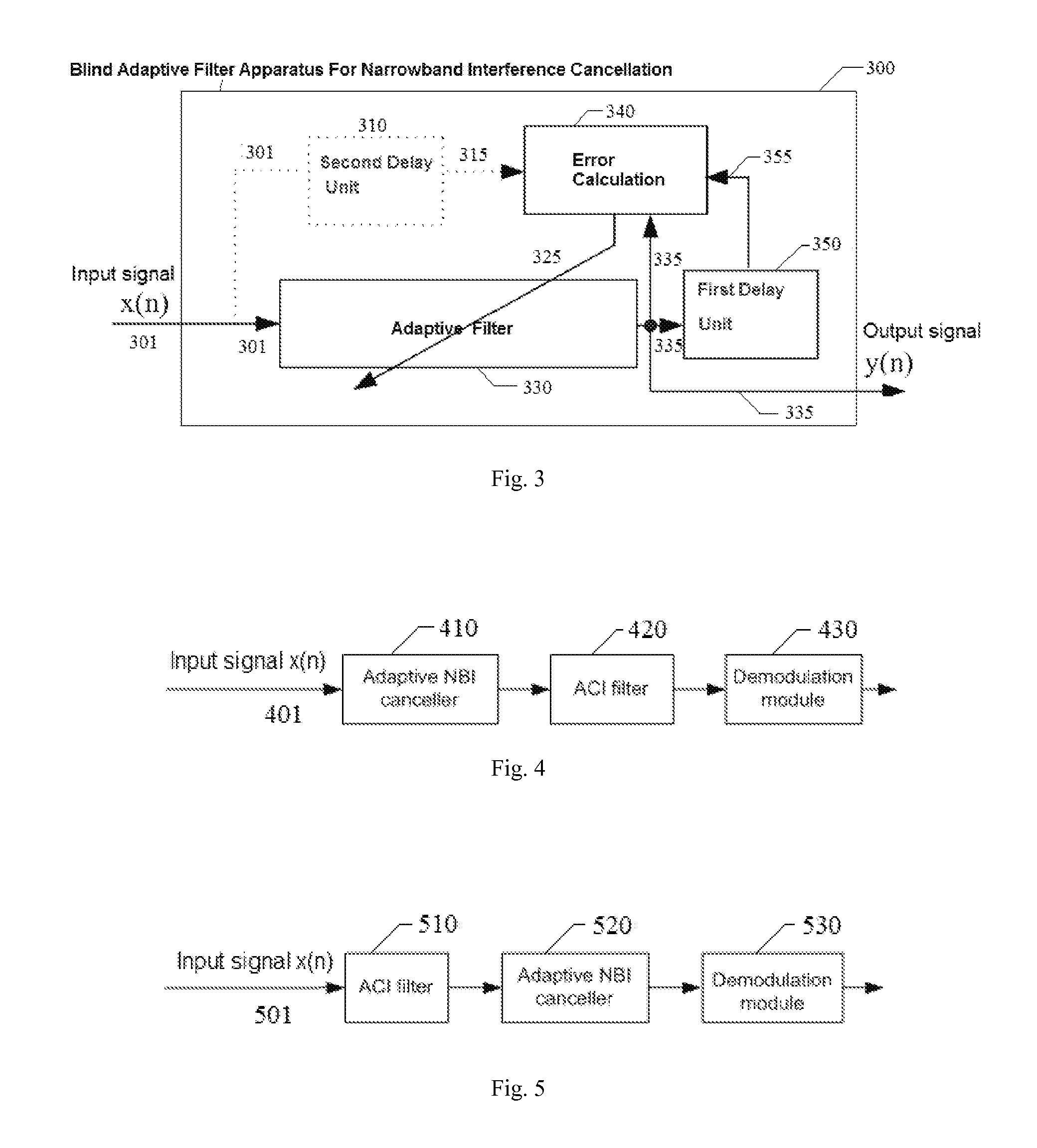
[0034]FIG. 3 illustrates a blind adaptive filter apparatus for narrowband interference cancellation consistent with the present invention. The blind adaptive filter includes an adaptive filter 330, a first delay unit 350, an error calculation unit 340, and a second delay unit 310.

[0035]The adaptive filter 330 receives an input signal x(n) 301, generating an output signal y(n) 335 through the filtering process. The adaptive filter 330 can be one be FIR filter or IIR filter. The inner architectures of FIR filter and IIR filter have been known by the technicians of this field and will not be described here. Besides, the technicians could choose different adaptive filter regarding to different applied scenarios.

[0036]The first delay unit 350 coupled to the adaptive filter 330 delays the...


PUM


Abstract

The present invention relates to a blind adaptive filter for narrowband interference cancellation, which includes an adaptive filter, a delay unit coupled to the adaptive filter for generating a delayed signal with a predetermined delay length from the output signal of the adaptive filter, and an error calculation unit coupled to the adaptive filter and the delay unit. The error calculation unit compares the output signal from the adaptive filter and the delayed signal from the delay unit to extract error information, and feedback the first error information to the adaptive filter. The first error information is formed of a transfer function including a number of coefficients, and used to adjust the adaptive filter and remove interference in the next input signal. The disclosed technique is also applicable in wideband receivers, as well as resisting multiple strong narrowband interferences having a frequency sweep rate of tens of milliseconds.

Description

CROSS REFERENCE TO RELATED PATENT APPLICATION[0001]The present application is the US national stage of PCT / CN2010 / 075662 filed on Aug. 3, 2010, which claims the priority of the Chinese patent application No. 201010199697.1 filed on Jun. 12, 2010, which application is incorporated herein by reference.BACKGROUND OF THE INVENTION[0002]1. Field of Invention[0003]The present invention relates to noise reduction in broadband communication, specifically to a blind adaptive filter for narrowband interference cancellation, and more specifically to a blind adaptive filter for narrowband interference cancellation which adjusts filter parameters according to the error information obtained after the processing of filtered output signal from the adaptive filter and the delayed output signal.[0004]2. Description of Related Arts[0005]The transport performance of a wideband mobile communication system can be seriously degraded by narrowband interferences from the same channel or from adjacent channe...

Claims


Application Information

Patent Timeline
Patent Type & Authority Patents(United States)
IPC IPC(8): H03D1/04
CPCH03H21/0021H03H2021/0094
Inventor HU, GANGNIE, YUANFEIWU, MEIWU
Owner MONTAGE TECHNOLOGY CO LTD
Learn More