Method and system for optical edge measurement

a technology of optical edge and optical edge, applied in image data processing, instruments, image enhancement, etc., can solve the problems of affecting the image acquisition system, affecting the image quality of the image, so as to achieve the effect of high reflection gain, low illumination power, and high signal in the imag

Inactive Publication Date: 2013-07-09
COGENETENS
View PDF19 Cites 9 Cited by
  • Summary
  • Abstract
  • Description
  • Claims
  • Application Information

AI Technical Summary

Benefits of technology

[0012]According to the present invention, preferably a retro reflective material or other suitably reflective material is placed behind the object to be measured as an optical background. A suitable front illumination system, typically adjacent to the camera(s) is used to illuminate the object and the reflective background. The reflection gain of the reflective material is preferably high, so that low illumination powers are required to achieve high signals in the image. The signal reflected off of the object is small because of the low illumination powers together with the mostly diffuse reflection properties, i.e., low gain, of the object. Overall the resultant image is bright in the areas thereof corresponding to the background and dark in the areas corresponding to the object. With this method, the problems posed by the reflection properties of the object near the edge do not come in to play in the resultant image, and the true edge can be found with relative ease.

Problems solved by technology

Optical measurements of the edges of manufactured objects are of great value in industry, but in practice such measurements are often difficult to accomplish with great accuracy or confidence.
There are often part to part and batch to batch manufacturing variations due to progressive wear and tear of the manufacturing tools, differences between several production lines that manufacture the same parts, and so on.
Further, when attempting to generate an image of an edge-comprising part, the edge reflectance characteristics of the part, which may include for example specular reflections, surface texture and other forms of optical interferences near the edge, can cause the edge or part thereof in the image to appear shifted relative to where the true mechanical edge of the part should appear in the image.
While effective to varying degrees, these methods nevertheless add significant complexity to the image acquisition systems.
Moreover, it is not possible in all applications to apply such techniques, for example when the objects being imaged are large objects such as for example some automotive parts, which would require large and complex back illumination systems.

Method used


Image

  • Method and system for optical edge measurement
  • Method and system for optical edge measurement
  • Method and system for optical edge measurement

Examples


first embodiment

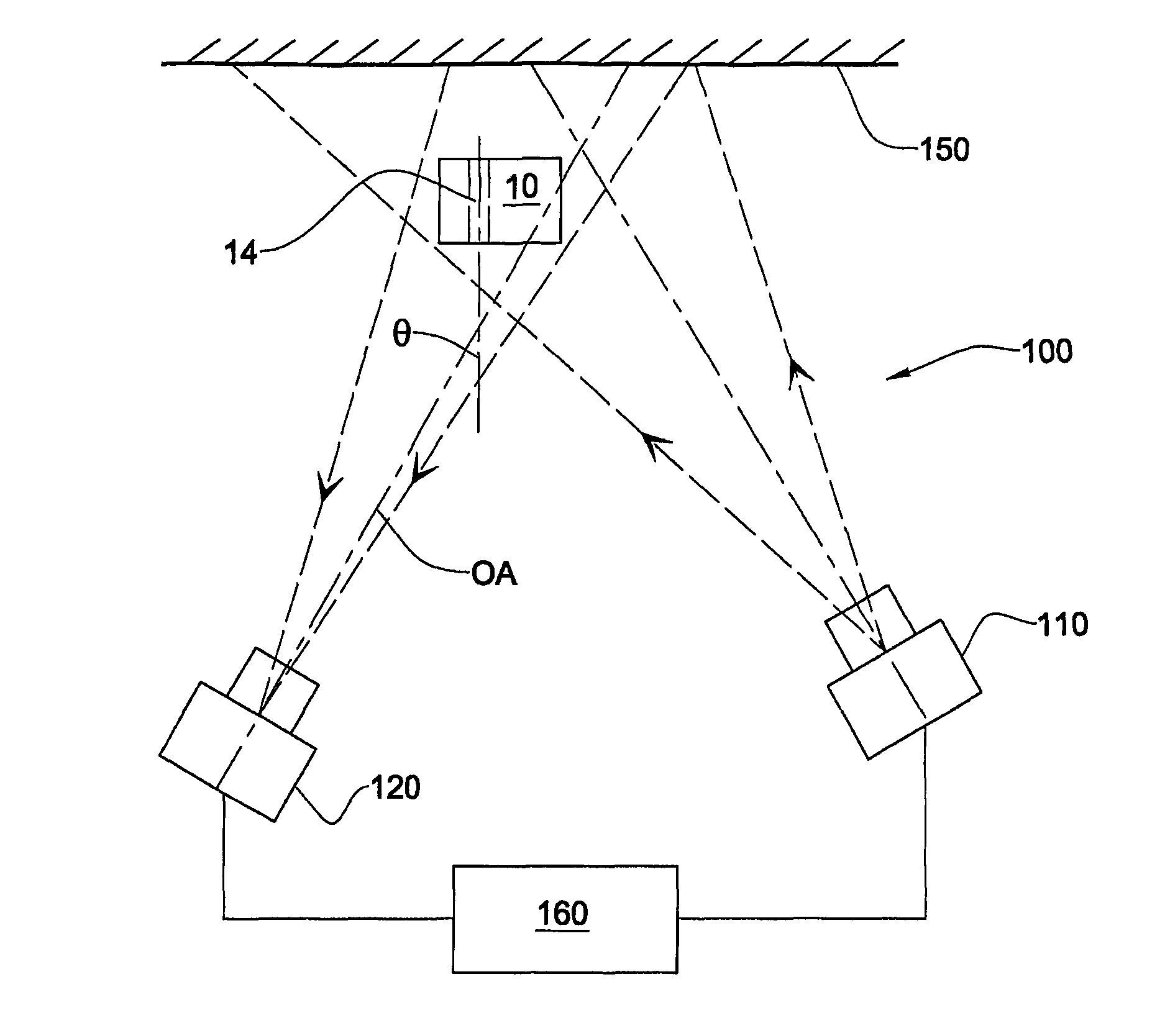
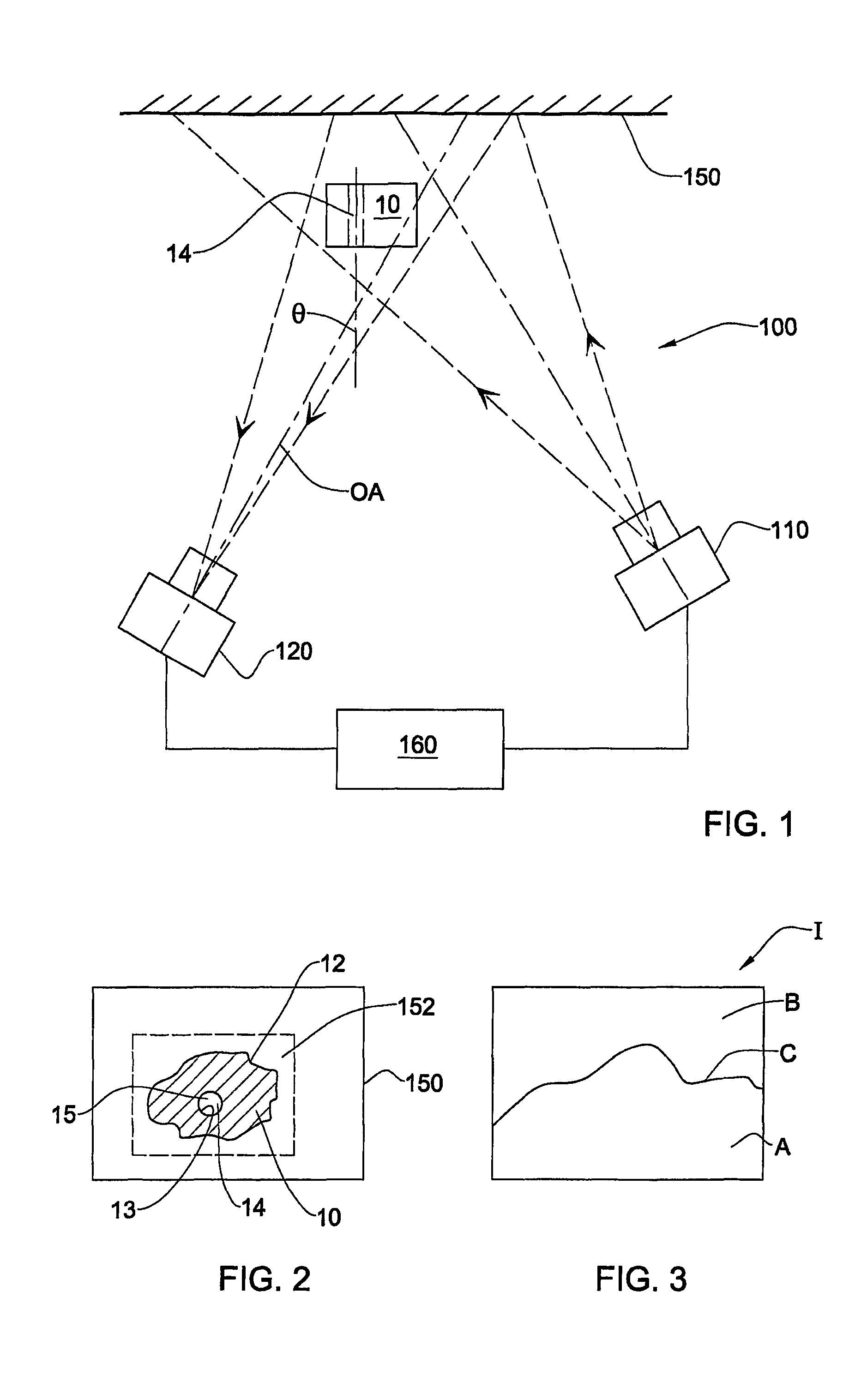
[0047]A system according to the invention is illustrated in FIG. 1. The system, generally designated with the numeral 100, comprises at least one illumination source 110, a light reflecting medium 150, and at least one optical image capturing device 120.

[0048]An object 10 to be imaged, typically comprising surfaces and edges 12 of interest, is placed in front of the medium 150, and arranged such that it is located between the medium 150 and the illumination source 110, and also between medium 150 and the image capturing device 120. In particular, the illumination source 110 is spatially arranged with respect to the object 10 and medium 150, such that, at least during operation of the system 100, the object 10, or at least a portion of the surface thereof comprising edges 12, and a part 152 of the medium 150 surrounding the edges 12 are illuminated by the source 110. While edges 12 are external edges of the object 10, the present invention also relates to internal edges, for example ...

second embodiment

[0096]the invention generally provides more accurate results when the edge being investigated is fully visible from the viewing axis of all the image capturing devices.

[0097]In this embodiment of the invention, the two images in each set of images are captured as images, substantially simultaneously, either by using two cameras or any other suitable image capturing devices 220A, 220B. In other variations of this embodiment, a single camera or other suitable image capturing device may be used, and moved between two positions relative to the object, the positions being similar to those occupied by devices 220A, 220B in FIG. 6, for example. In such variations, the precise position of the single image capturing device is preferably accurately reproduced for each set of images taken. Alternatively, there are some methods, for example the bundle adjustment method used in photogrammetry, in which the 3D location of the fiducial or datum points and camera positions and locations are calcula...


PUM


Abstract

Edge data for an object are obtained by placing the object in front of a medium that has greater reflectance than the object, and both are illuminated by a light source. The contrast in image intensity obtained between the object and background enables the edges of the object to be determined.

Description

CROSS-REFERENCE[0001]This is a National Phase Application filed under 35 U.S.C. 371 of International Application No. PCT / IL2005 / 000660, filed Jun. 20, 2005, claiming the benefit under 35 USC 119(e) of U.S. Provisional Application No. 60 / 623,769, filed Nov. 1, 2004, the entire contents of each of which is hereby incorporated herein by reference in its entirety.FIELD OF THE INVENTION[0002]This invention relates to optically-based methods and systems for dimensional measurement of objects. In particular, the invention is directed to measurements relating to free edges of such objects, especially where the objects are highly reflective and / or textured.BACKGROUND OF THE INVENTION[0003]Optical measurements of the edges of manufactured objects are of great value in industry, but in practice such measurements are often difficult to accomplish with great accuracy or confidence. Industrially manufactured objects such as automotive metal parts, plastic parts and so on typically vary in their o...

Claims


Application Information

Patent Timeline
Patent Type & Authority Patents(United States)
IPC IPC(8): G01B11/14G06V10/145
CPCG01B11/2433G01N21/8806G06K9/2036G06T7/0083G01N2021/8896G06T2207/10016G06T2207/30164G06T7/12G06V10/145
Inventor SEGEV, AVNER
Owner COGENETENS
Why Eureka
Try Eureka