
Articulating band saw and method

a band saw and articulating technology, applied in the direction of chain saws, band saws, manufacturing tools, etc., can solve the problems of direct injury of dangerous cold cutting of decommissioned oil and gas pipelines, and damage to workers directly involved in hot work or cold cutting, so as to reduce or minimize reduce or eliminate the amount of material, and reduce the use of coolant/lubricant. and potential environmental contamination

Active Publication Date: 2013-07-02
AES EOT EQUIP HLDG LLC
View PDF56 Cites 27 Cited by
  • Summary
  • Abstract
  • Description
  • Claims
  • Application Information

AI Technical Summary

Benefits of technology

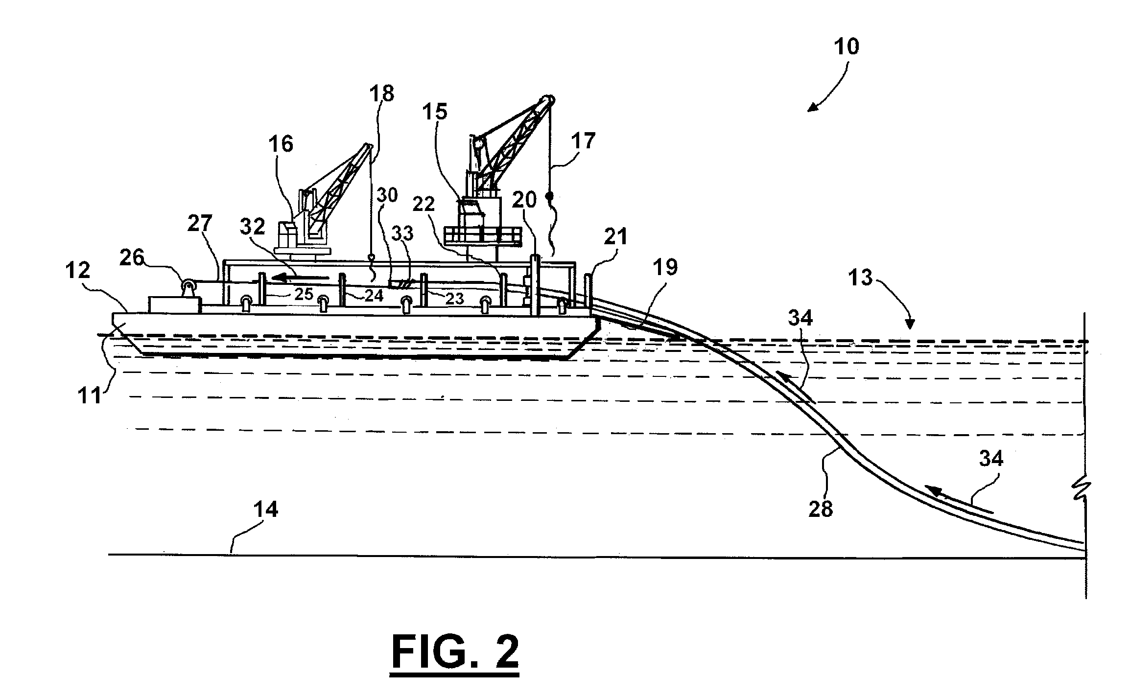
The present invention is about a cutting system that can be remotely controlled to improve safety during cutting operations. The system uses hydraulic actuators to move the cutting blade to different positions, allowing for easy positioning or repositioning of the blade. This way, the system can be used without the need for personnel to be in or near the cutting zone, reducing the risk of injury and exposure to sparks or flying metal debris. Additionally, the use of a separate hydraulic control panel eliminates the need for hot work, which can ignite residual hydrocarbons and potentially cause injury. Overall, the invention improves safety by minimizing or eliminating the need for personnel to be exposed to these risks.

Problems solved by technology

Cold cutting of decommissioned oil and gas pipelines can be dangerous if for example personnel are required to stand near or participate in the cutting operation.
Workers can be injured because of sparking or flying metal debris.
Workers directly involved in hot work or cold cutting can be injured by falling material such as sections of material or pipe that have been cut and lifted by a vessel or platform crane.

Method used


Image

  • Articulating band saw and method
  • Articulating band saw and method
  • Articulating band saw and method

Examples


example cutting

Job

[0124]Below is provided various steps in an example cutting job.

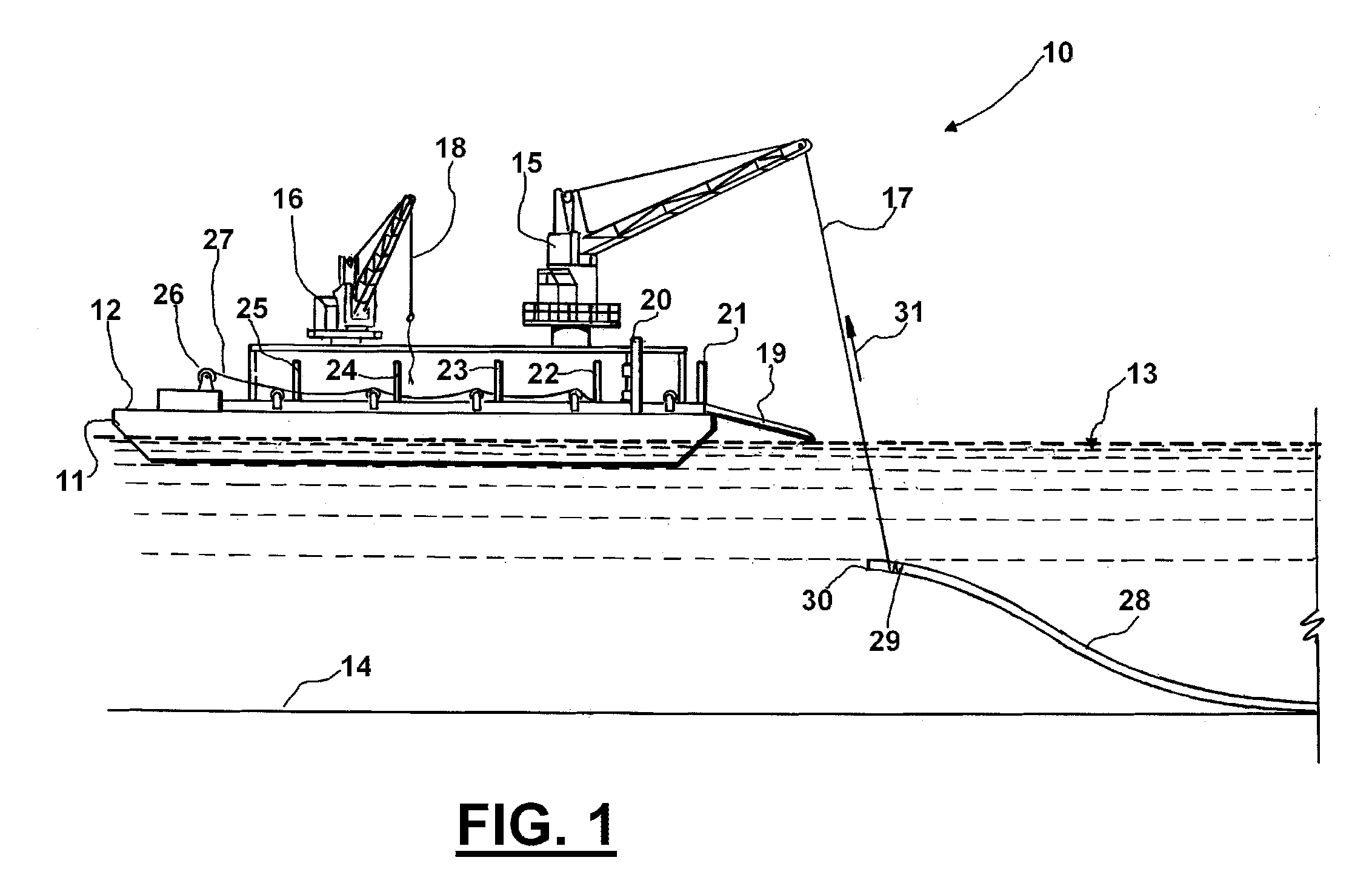
[0125]1. Job to be performed is discussed at length with Customer and associated engineers. Details including, but not limited to, tooling placement on vessel 11, shipboard power requirements, water depth, pipe sizes to be cut, offshore location, departure dock and safety orientation.

[0126]2. Articulating Band Saw 20 and support equipment can be prepared and function tested prior to transport. All items can be dispatched through a predetermined shipment carrier to the departure dock.

[0127]3. Articulating Band Saw 20 and support equipment can be transported via customer's supply vessel to the work location that could be a platform, drilling rig, drill ship, work barge 11, dive boat, or lift boat.

[0128]4. Equipment is offloaded via work platform crane 15 and placed on deck 12 in accordance with the vessel Captain or tool pusher's instructions.

[0129]5. All equipment is inspected by operator 61 personnel for transport da...


PUM

PropertyMeasurementUnit
hydraulic pressureaaaaaaaaaa
feed rate pressureaaaaaaaaaa
heightaaaaaaaaaa

Abstract

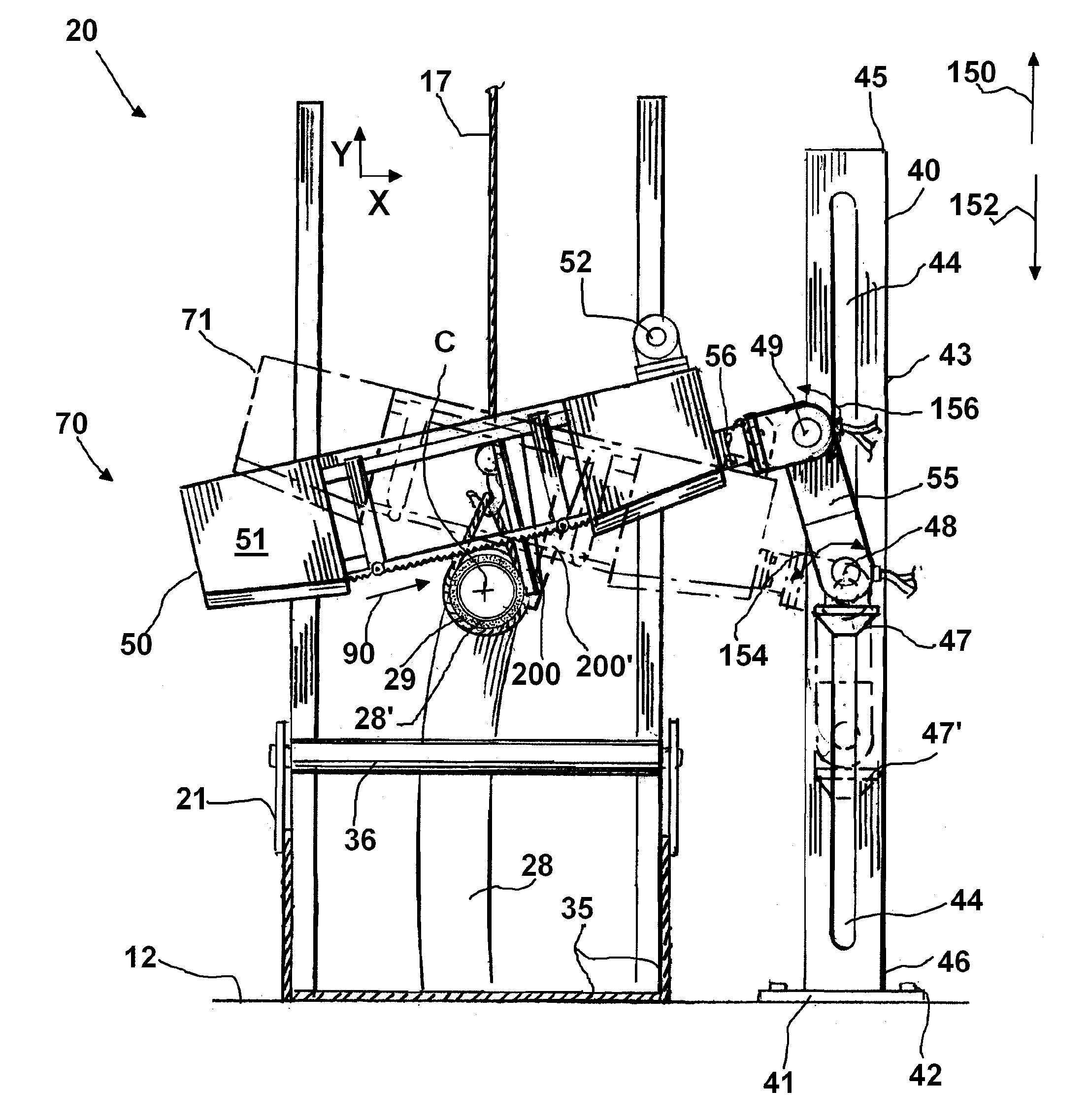
An articulating band saw apparatus provides a frame that includes a vertically extending section having upper and lower end portions. An elevator moves between the upper and lower end portions of the frame. A first hydraulic actuator is supported on the elevator for movement therewith. A first arm provides arm end portions, the first arm supported by the first hydraulic actuator. An end of the first arm supporting a second hydraulic actuator that is spaced away from the first hydraulic actuator. The second hydraulic actuator supports a second arm. An endless band type saw is mounted on the free end of the second arm generally opposite the second actuator. The band saw is movable by articulation of the first and second actuators and resulting movement of the first and second arms. In one embodiment, the band saw is a diamond wire saw.

Description

CROSS-REFERENCE TO RELATED APPLICATIONS[0001]This is a continuation application of PCT Patent Application Serial Number PCT / US2009 / 050014, having international filing date of Jul. 9, 2009, which PCT Patent application in the United States was a continuation-in-part of U.S. patent application Ser. No. 12 / 170,004, filed Jul. 9, 2008 (issuing as U.S. Pat. No. 7,645,093 on Jan. 12, 2010).[0002]Priority of each of the above referenced is hereby claimed and each of the above referenced applications are incorporated herein by reference.STATEMENT REGARDING FEDERALLY SPONSORED RESEARCH OR DEVELOPMENT[0003]Not applicableREFERENCE TO A “MICROFICHE APPENDIX”[0004]Not applicableBACKGROUND[0005]The present invention relates to a method and apparatus for salvaging and cutting decommissioned oil and gas pipelines into sections. More particularly, the present invention relates to a method and apparatus for cutting target material such as decommissioned oil and gas pipelines into sections as they are...

Claims


Application Information

Patent Timeline
Patent Type & Authority Patents(United States)
IPC IPC(8): B27B13/00
CPCB63B35/03F16L1/202B23D53/045F16L1/207B27B13/12B27B13/16B27B13/02B23D53/04B23D55/088Y10T83/283Y10T83/722Y10T83/7145Y10T83/7208Y10T83/7195B23D57/0023Y10T83/263
Inventor CLARK, II, GALEN R.MARTIN, MICHAEL TODDSIEMS, GARY L.
Owner AES EOT EQUIP HLDG LLC
Learn More