Eureka AIR delivers breakthrough ideas for toughest innovation challenges, trusted by R&D personnel around the world.

Top electrode templating for DRAM capacitor

Inactive Publication Date: 2013-05-07
INTERMOLECULAR +1
View PDF3 Cites 5 Cited by
  • Summary
  • Abstract
  • Description
  • Claims
  • Application Information

AI Technical Summary

Benefits of technology

The present invention involves a new design for a capacitor structure. The structure includes a high k dielectric material and a second electrode material that is a metal oxide layer. This second electrode material can be a single layer or a combination of a metal oxide layer and a metal layer. The metal oxide layer has a high work function and is compatible with rutile phase TiO2 high k dielectric materials. The technical effect of this design is that it provides a more efficient and reliable capacitor structure, which can be used in various electronic devices.

Problems solved by technology

However, high temperature processes are undesirable in the manufacture of DRAM devices.
However, oxygen-rich phases (MoO2+x) degrade the performance of the MoO2 electrode because they do not promote the deposition of the rutile-phase of TiO2 and have higher resistivity than MoO2.
The use of crystalline MoO2 as a second electrode in MIM DRAM capacitors has been difficult due to a number of problems.
As discussed above, MoO2 is sensitive to oxidation to form oxygen-rich compounds that negatively impacts its performance as an electrode material.
The reducing atmosphere anneal processes discussed previously with respect to the use of crystalline MoO2 as a first electrode are not an option at this stage of the device manufacture because they would degrade the performance of the dielectric layer through the formation of oxygen vacancies.
TiO2 high k dielectric materials are especially sensitive to processing conditions and increases in the leakage current are observed, likely due to the formation of oxygen vacancies.
The asymmetric stack provides a number of problems.
First, Ru is expensive and increases the cost of manufacturing for the DRAM device.
Second, the leakage current of the MIM DRAM device increases at high temperatures (i.e. 90 C) to above the desired target of −7 A cm−2 at 1V.

Method used


Image

  • Top electrode templating for DRAM capacitor
  • Top electrode templating for DRAM capacitor
  • Top electrode templating for DRAM capacitor

Examples


Embodiment Construction

[0026]A detailed description of one or more embodiments is provided below along with accompanying figures. The detailed description is provided in connection with such embodiments, but is not limited to any particular example. The scope is limited only by the claims and numerous alternatives, modifications, and equivalents are encompassed. Numerous specific details are set forth in the following description in order to provide a thorough understanding. These details are provided for the purpose of example and the described techniques may be practiced according to the claims without some or all of these specific details. For the purpose of clarity, technical material that is known in the technical fields related to the embodiments has not been described in detail to avoid unnecessarily obscuring the description.

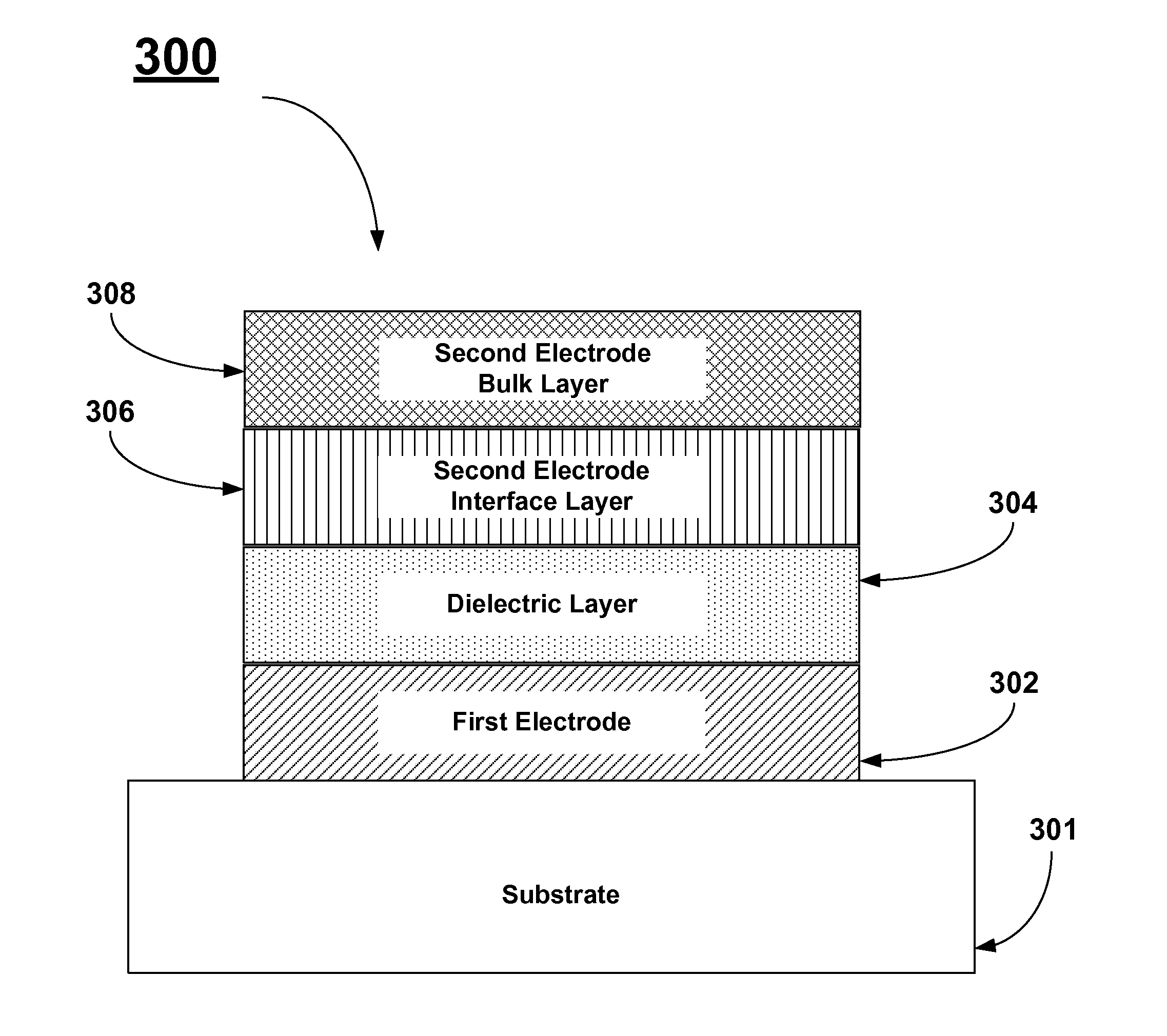
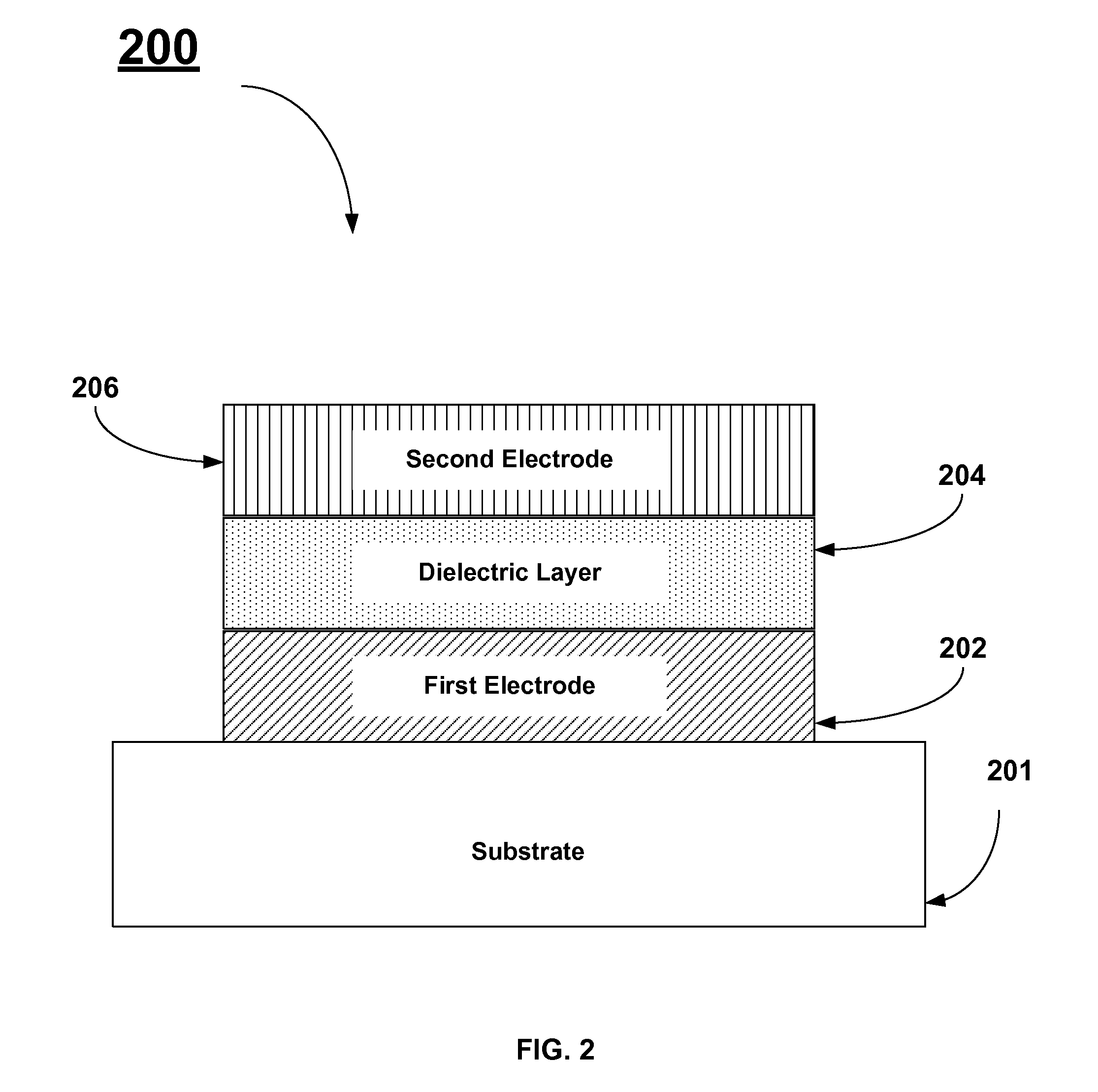
[0027]In FIGS. 2, 3, 5, and 6 below, a capacitor stack is illustrated using a simple planar structure. Those skilled in the art will appreciate that the description and teachi...


PUM


Abstract

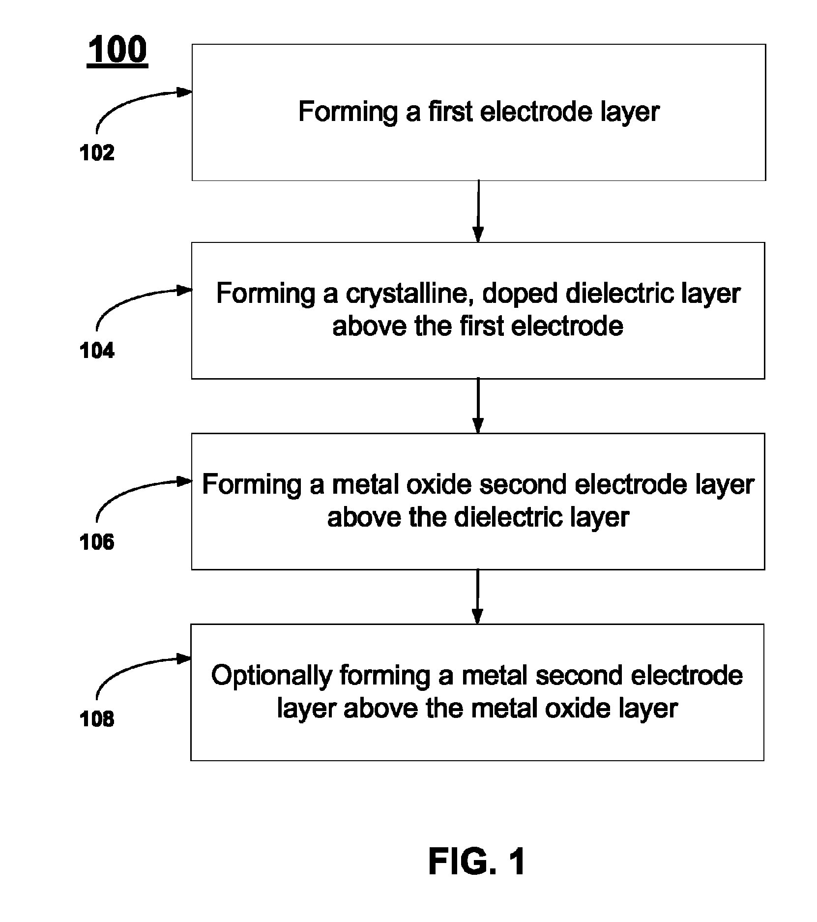
A method for forming a DRAM MIM capacitor stack having low leakage current involves the use of a first electrode that serves as a template for promoting the high k phase of a subsequently deposited dielectric layer. The high k dielectric layer comprises a doped material that can be crystallized after a subsequent annealing treatment. A metal oxide second electrode layer is formed above the dielectric layer. The metal oxide second electrode layer has a crystal structure that is compatible with the crystal structure of the dielectric layer. Optionally, a second electrode bulk layer is formed above the metal oxide second electrode layer.

Description

[0001]This document relates to the subject matter of a joint research agreement between Intermolecular, Inc. and Elpida Memory, Inc.FIELD OF THE INVENTION[0002]The present invention relates generally to the use of top electrodes that have crystal structures that are compatible with rutile phase TiO2 high k dielectric materials used in capacitors used in Dynamic Random Access Memory (DRAM) devices.BACKGROUND OF THE INVENTION[0003]Dynamic Random Access Memory utilizes capacitors to store bits of information within an integrated circuit. A capacitor is formed by placing a dielectric material between two electrodes formed from conductive materials. A capacitor's ability to hold electrical charge (i.e., capacitance) is a function of the surface area of the capacitor plates A, the distance between the capacitor plates d (i.e. the physical thickness of the dielectric layer), and the relative dielectric constant or k-value of the dielectric material. The capacitance is given by:[0004]C=κɛo⁢...

Claims


Application Information

Patent Timeline
IPC IPC(8): H01L21/8242
CPCH01L27/10852H01L28/40H01L28/75H01L21/02356H01L21/02194H01L21/0228H01L21/02304H01L21/02186H10B12/033
Inventor MALHOTRA, SANDRACHEN, HANHONGDEWEERD, WIMODE, HIROYUKI
Owner INTERMOLECULAR
Why Eureka
Eureka Blog
Learn More