
Inkjet printing fluid

a technology of printing fluid and inkjet, which is applied in the field of inkjet printing fluid, can solve the problems of long milling operation, detrimental effect of optical density and gloss in printed images, pigment-based inks often require a long milling operation, etc., and achieve the effect of short time and long time intervals

Active Publication Date: 2013-04-30
EASTMAN KODAK CO
View PDF32 Cites 29 Cited by
  • Summary
  • Abstract
  • Description
  • Claims
  • Application Information

AI Technical Summary

Benefits of technology

The solution achieves durable images with improved short-term and long-term abrasion resistance and stable performance in high-frequency thermal inkjet printing and continuous inkjet systems, reducing filter plugging and maintaining fluid stability over extended periods.

Problems solved by technology

However, pigment-based inks have a number of drawbacks.
Pigment-based inks often require a lengthy milling operation to produce particles in the sub-micron range needed for most modern ink applications.
If the pigment particles are too large light scattering can have a detrimental effect on optical density and gloss in the printed image.
A second drawback of pigmented inks is their durability after printing, especially under conditions where abrasive forces have been applied to the printed image.
Pigment-based inks typically reside at the surface of the imaging receiver to which they are printed and this makes the printed images particularly susceptible to abrasive forces.
At short time intervals the binder film formation is incomplete and the resulting pigment cake is particularly susceptible to abrasive forces.
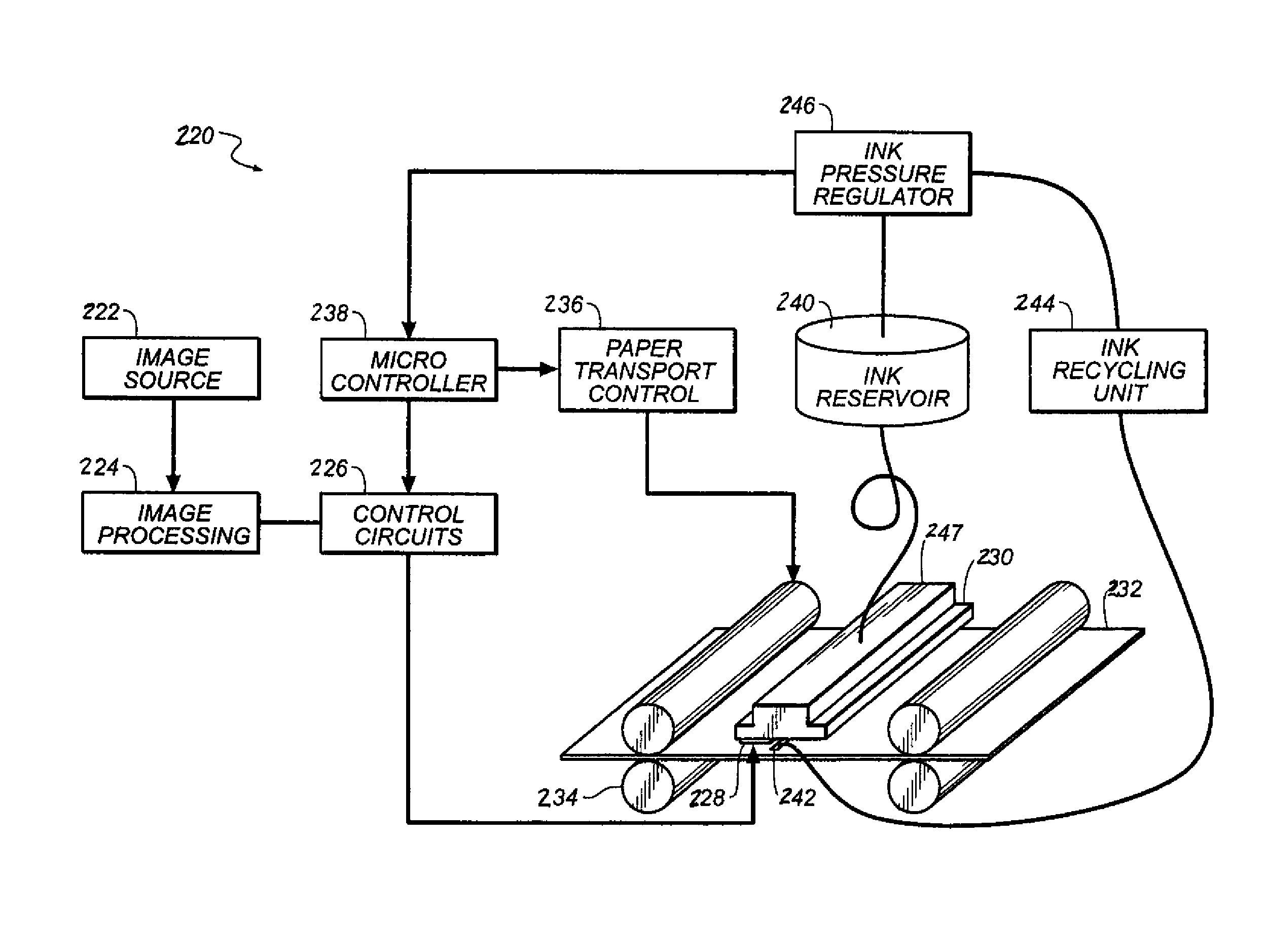
Images printed from an inkjet printer are also susceptible to abrasive forces as the image receiver is advanced through the printer.
In either case, the mechanical abrasion caused by the spur wheel occurs at short time intervals on the order of a few seconds after printing and results in a defect that is objectionable to the eye.
Further, in some cases, the incomplete polymer binder film formation results in a tacky surface that can stick to such surfaces within the printer that transport the printed image.
Pigmented inks for inkjet printing have been formulated with acrylic polymers; however, the acrylic polymers alone are insufficient in providing durable images that resist scratches and other forms of physical abuse.
Although polyurethanes are known for their excellent abrasion resistance, they also have a number of drawbacks.
US H2113H, and US Publication Numbers 2004 / 0130608 and 2004 / 0229976 are particularly difficult to jet from a thermal inkjet printhead at high tiring frequencies.
Clear inks formulated with polyurethanes, however, also suffer from the same short term durability issues as colored inks since they have many components in common with their colored ink counterparts.
In addition, the application of a clear ink increases the total amount of water applied to the receiver and therefore slows down the drying of the imaged area of the prints.
Although the application of clear ink can improve the long term durability, its application can adversely affect the short term durability due to the increased water load on the receiver.
Both pigment and clear inks can be difficult to jet through inkjet printheads having small nozzle diameters especially by the thermal inkjet printing process.
However, this high frequency firing often comes at the cost of variability in the firing velocity, which leads to poor image quality in the final printed image.
In addition, the demands of current thermal inkjet printing require that the nozzles fire for a large number of firings during the life-time of a printer.
Although there have been many recent advances in the art of dye-based inkjet inks, such inks still suffer from deficiencies such as low optical densities on coated glossy paper and poor light-fastness.
When water is used as the carrier, such inks also generally suffer from poor water fastness and poor smear resistance.
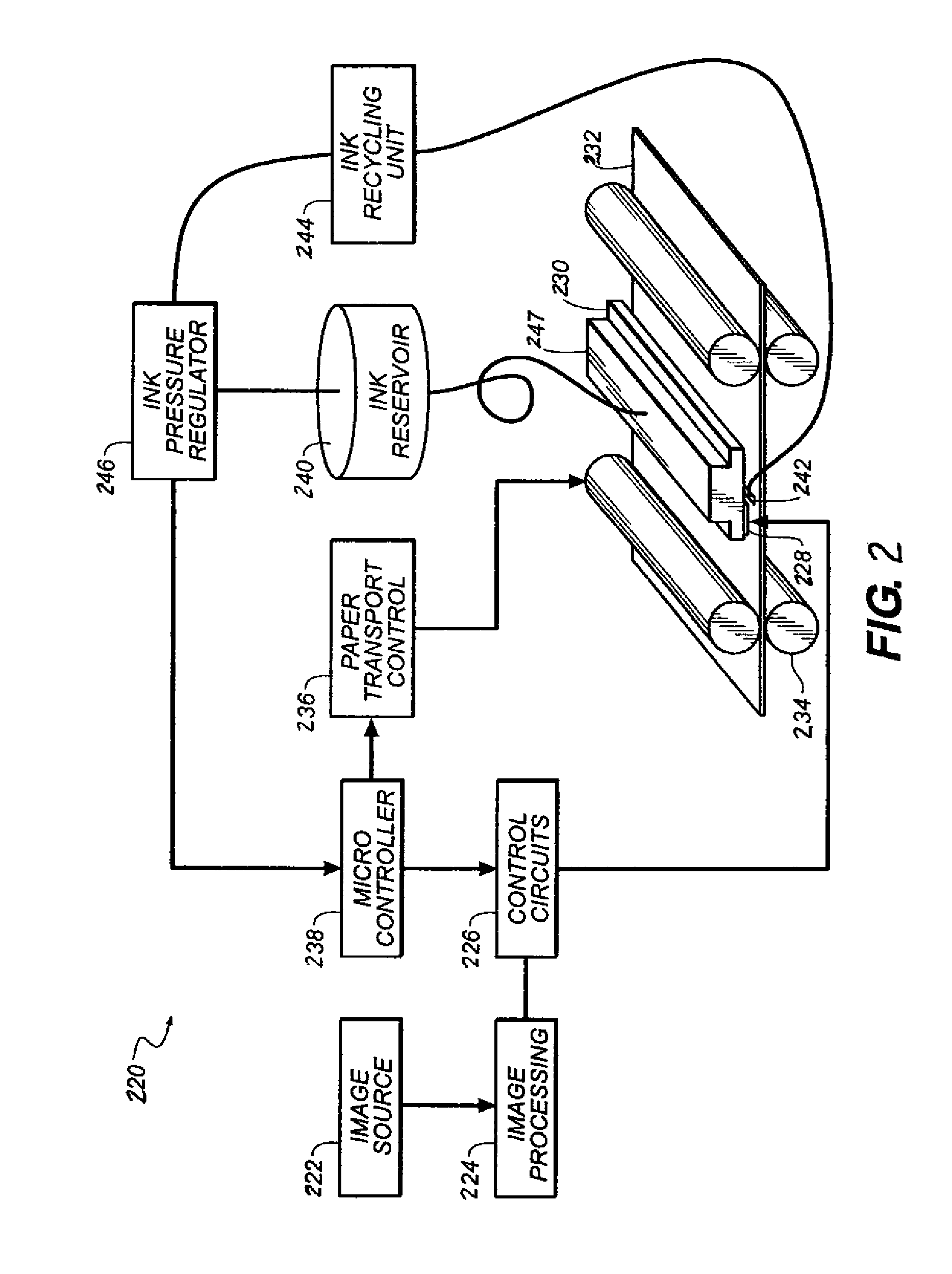
It has been discovered, however, that severe filter plugging issues may be encountered when running pigment inks in a CIJ fluid system, requiring frequent change of filters, e.g., over the time period of a few hours vs. a few months for dye-based inks.
The consequence of filter plugging is the loss of fluid pressure and fluid jets, leading to system shutdown.
Further investigation has discovered that the gear pump commonly used in the fluid system to maintain fluid pressure with minimal pulsation can cause agglomeration of pigment particles, leading to filter clogging and system shutdown.
Further, addition of polyurethanes can also substantially increase the viscosity of a printing fluid, and cause printing fluids to become destabilized upon recirculation, which may be especially undesirable for continuous inkjet printing applications.

Method used


Image

  • Inkjet printing fluid
  • Inkjet printing fluid
  • Inkjet printing fluid

Examples


example 1

Synthesis of the Inventive Polyurethanes PU-1 through PU-19

PU-1:

[0085]In a round bottom flask equipped with thermometer, stirrer, water condenser, and a vacuum outlet was placed 77.16 g (0.1187 moles) of Terathane 650 polyether glycol having a average Mn=650 (Aldrich 25190-06-1, 48.56 g (0.3620 moles) of 2,2-bis(hydroxymethyl) propionic acid (DMPA), 22.69 g 90,2518 moles) of 1,4-butane diol, 350 g of ethyl acetate (EA), and 0.85 g of dibutyl tin dilaurate. The temperature was adjusted to 65° C., and when a homogeneous solution was obtained, 162.82 g (0.7523 moles) of isophorone diisocyanate (IPDI) was slowly added, followed by 10 mL EA. The temperature was raised to 78° C. and maintained overnight to complete the reaction. The reaction mixture was diluted with 65 g of isopropanol (IPA) before being neutralized with a mixture of 45.13 g of 45 wt. % KOH solution and 45 g of distilled water to achieve 100% stoichiometric ionization based on the amount of DMPA. Under high shear, 918 g o...

example 2

Synthesis of the Comparative Polyurethanes CPU-1 through CPU-9

[0088]CPU-1 through CPU-6 were prepared in a similar manner to the inventive examples. CPU-1 through CPU-4 do not contain any Y2 diol and are stable dispersions. CPU-5 and CPU-6 contained about 13% of 1,4 butane diol and the resultant dispersions were less stable as reflected by filter plugging or excessive amount of foam formed during solvent removing under vacuum. CPU-5 and CPU-6 are considered to be non-manufacturable.

[0089]CPU-7 was prepared in accordance with the recipe disclosed in U.S. Pat. No. 6,508,548. CPU-8 was prepared in accordance with the recipe disclosed in U.S. Pat. No. 6,533,408 (PU-2). CPU-9 was prepared in accordance with the recipe disclosed in U.S. Pat. No. 6,533,408 (PU-3). All three dispersions had to be diluted very significantly to lower solids for filtration. They are considered to be less manufacturable.

[0090]

TABLE 2IDY1 diolWt %Y2 diolWt %ANMw / MnCPU-1Terathane 200044.1None—80 64800 / 13900CPU-2T...

example 3

Preparation of Polymeric Dispersant P-1

[0091]A 5-liter, three-necked round bottom flask equipped with a mechanical stirrer, a reflux condenser, and a gas inlet was charged with 225 g of 1-methoxy-2-propanol and was sparged with nitrogen. Akzo-Nobel Chemicals, Inc., initiator Perkadox AMBN-GR (1.9 g) was added with stirring. A reactant reservoir was charged with 225 g of 1-methoxy-2-propanol, 23.4 g of 1-dodecanethiol, 203.5 g of benzyl methacrylate, 165.0 g of stearyl methacrylate, and 181.5 g of methacrylic acid, and the solution was degassed by nitrogen sparging. AMBN-GR (7.7 g) was added and mixed in. The reactor temperature was raised to 77° C. and the reactants were pumped from the reservoir at about 2.3 mL / min over a 360-min period. The reaction mixture was stirred for at least 12 h at about 77° C. The polymer was neutralized to completion with dimethylaminoethanol and stirred for 45 min. The reaction mixture was diluted with 2,580 g of water and filtered through a Pall Corp. ...


PUM

PropertyMeasurementUnit
molecular weightaaaaaaaaaa
weight average molecular weightaaaaaaaaaa

Abstract

An inkjet printing fluid composition including water and a water dispersible polyurethane additive of the general formula of (I)wherein Z is the central portion of a monomer unit that is the polymerization product of a diisocyanate; X1—Y1—X1 represents one or more soft segments wherein Y1 represents the central portion of a unit that is the polymerization product of a diamine or diol prepolymer having a molecular weight of greater than 300 Daltons; W is the central portion of one or more units containing an acid group; X2—Y2—X2 represents one or more hard segments wherein Y2 represents the central portion of a unit that is the polymerization product of a C2-C8 diol or diamine having a molecular weight of less than 250 Daltons; and X1, V and X2 can be the same or different and are an —O— or —N— atom; and further wherein the polyurethane additive has a weight average molecular weight of at least 6,000 Daltons and a sufficient number of acid groups to provide an acid number greater than 35, and the one or more X2—Y2—X2 hard segments are present at from 1 wt % to less than 13 wt % of the polyurethane additive. Also disclosed is a method for printing an inkjet image including I) providing an inkjet printing fluid according to the invention; and II) jetting the inkjet printing fluid in the form of ink drops onto a recording element to form a printed image.

Description

CROSS-REFERENCE TO RELATED APPLICATIONS[0001]Reference is made to commonly assigned U.S. application Ser. No. 12 / 872,018, filed Aug. 31, 2010 (Publication No. 2012 / 0050415), directed towards “Recirculating Fluid Printing System and Method,” the disclosure of which is incorporated by reference herein in its entirety.FIELD OF THE INVENTION[0002]The invention relates generally to the field of inkjet printing fluids, including pigmented and clear inks, and in particular to inks which are useful for thermal inkjet printing and continuous inkjet printing. More specifically, the invention relates to pigmented and clear inks for high-speed inkjet printing which result in durable images.BACKGROUND OF THE INVENTION[0003]Inkjet printing is a non-impact method for producing printed images by the deposition of ink droplets in a pixel-by-pixel manner to an image-recording element in response to digital signals. There are various methods that can be used to control the deposition of ink droplets o...

Claims


Application Information

Patent Timeline
Patent Type & Authority Patents(United States)
IPC IPC(8): G01D11/00
CPCC09D11/102C09D11/326C09D11/322
Inventor FALKNER, CATHERINE A.BRUST, THOMAS B.WANG, YONGCAIYAU, HWEI-LINGROBELLO, DOUGLAS R.
Owner EASTMAN KODAK CO
Learn More