
Hydrosilylation catalysts

a catalyst and hydrosilylation technology, applied in physical/chemical process catalysts, organic compounds/hydrides/coordination complexes catalysts, other chemical processes, etc., can solve the problem of reducing the performance of precious metal complex catalysts in end-use applications, forming undesirably odoriferous by-product compounds, and inefficient catalytic performance of precious metal complex catalysts

Inactive Publication Date: 2013-04-09
CORNELL UNIVERSITY +1
View PDF11 Cites 27 Cited by
  • Summary
  • Abstract
  • Description
  • Claims
  • Application Information

AI Technical Summary

Benefits of technology

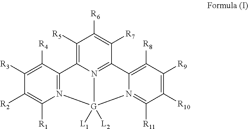
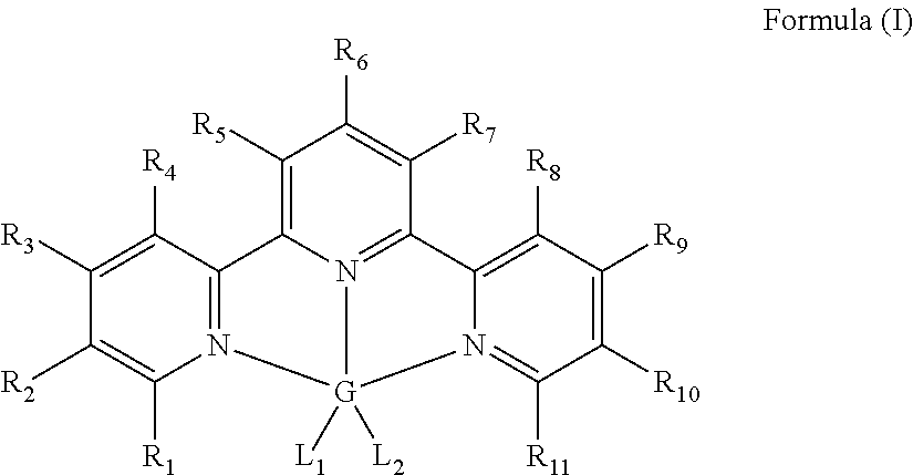
The present invention provides a new metal complex (Formula I) and a process for using it to hydrosilylate compounds containing unsaturated groups. The metal complex contains a central metal such as Mn, Fe, Ni, or Co, and is surrounded by a group of ligands consisting of hydrogen, alkyl, substituted alkyl, aryl, substituted aryl, or inert functional groups. The ligands can form a ring structure and may contain heteroatoms. The metal complex is effective in catalyzing the hydrosilylation reaction, where a silyl hydride reacts with the unsaturated compound to produce the desired product. The process can involve a solvent and can be carried out at room temperature. The hydrosilylation product contains the metal complex, which can be removed.

Problems solved by technology

One disadvantage is that the precious metal complex catalysts are inefficient in catalyzing certain reactions.
When the hydrosilylation reaction is completed, this excess allyl polyether must either be: (A) removed by an additional step, which is not cost-effective, or (B) left in the product which results in reduced performance of this product in end-use applications.
Additionally, the use of an excess amount of allyl polyether typically results in a significant amount of undesired side products such as olefin isomers, which in turn can lead to the formation of undesirably odoriferous by-product compounds.
Another disadvantage of the precious metal complex catalysts is that sometimes they are not effective in catalyzing hydrosilylation reactions involving certain type of reactants.
It is known that precious metal complex catalysts are susceptible to catalyst poisons such as phosphorous and amine compounds.
Accordingly, for a hydrosilylation involving unsaturated amine compounds, the precious metal catalysts known in the art are normally less effective in promoting a direct reaction between these unsaturated amine compounds with Si-hydride substrates, and will often lead to the formation of mixtures of undesired isomers.
Further, due to the high price of precious metals, the precious metal-containing catalysts can constitute a significant proportion of the cost of silicone formulations.
However, unwanted by products such as the unsaturated silyl olefins, which are resulted from dehydrogenative silylation, were formed as well.
However, one of the limitations of these catalysts is that they are only effective with the aforementioned primary and secondary phenyl-substituted silanes, and not with, for example, tertiary or alkyl-substituted silanes such as Et3SiH, or with alkoxy substituted silanes such as (EtO)3SiH.

Method used


Image

  • Hydrosilylation catalysts
  • Hydrosilylation catalysts
  • Hydrosilylation catalysts

Examples


example 1

Preparation of Iron (II) Terpyridine Dichloride

[0060]In an inert atmosphere, a scintillation vial was charged with 0.233 g (1.0 mmol) of terpyridine and 0.126 g (1.0 mmol) of ferrous dichloride. Approximately 20 mL of dry THF was added to the mixture and the resulting slurry was stirred overnight. Then approximately 50 mL of pentane was added resulting in precipitation of a purple solid. The solid was collected and dried in vacuo to yield 0.345 g (96%) of the iron (II) terpyridine dichloride. The sample was compared to previously reported compound. See Reiff, William M.; Erickson, N. E.; Baker, Willie Arthur, Jr. Mono(2,2′,2″-terpyridine) complexes of iron(II). Inorganic Chemistry (1969), 8(9), 2019-21.

example 2

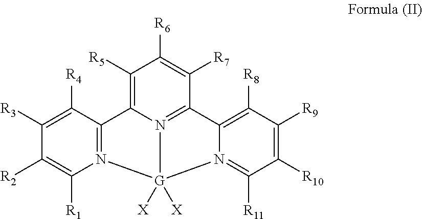
Preparation of Bis[(trimethylsilyl)methyl]iron(II)terpyridine

[0061]In an inert atmosphere, a round bottomed flask was charged with 0.360 g (1.0 mmol) of terpyridine iron dichloride, and approximately 10 mL of diethyl ether. The flask was chilled to −35° C. A solution containing 0.188 g (2.0 mmol) of LiCH2SiMe3 was added followed by approximately 10 mL of diethyl ether. A color change occurred immediately upon addition and the resulting slurry was stirred and allowed to warm to ambient temperature. After stirring for one hour, the reaction mixture was filtered through Celite® and the volatiles were removed in vacuo. The resulting paramagnetic purple solid was washed with approximately 5 mL of cold pentane yielding 0.400 g (87%) of the title compound. 1H NMR (benzene-d6, 20° C.): δ=319.80 (bs, 1H), 194.68 (bs, 2H), 154.65 (bs, 2H), 115.20 (bs, 2H), 59.36 (bs, 2H), 38.56 (bs, 2H), 8.73 (bs, 18H).

example 3

Hydrosilylation of 1-hexene with Et3SiH using Bis[(trimethylsilyl)methyl]iron(II)terpyridine catalyst

[0062]A stock solution containing 5 mg of bis[(trimethylsilyl)methyl]iron(II) terpyridine and 0.60 g of toluene was charged into a scintillation vial in a nitrogen filled drybox. The toluene was removed in vacuo followed by addition of 0.114 g (1.4 mmol) of 1-hexene. To the same vial, 0.105 g (0.90 mmol) of Et3SiH was added. The vial was sealed with a small amount Krytox grease and electrical tape, removed from the drybox and placed in a 95° C. oil bath. The concentration of the iron complex was less than 0.1 mol % relative to the silane, and the reaction time was 4 hours to achieve greater than 90% conversion to (CH3CH2)3Si—(CH2)5—CH3. Less than 5% each of (CH3CH2)3Si—CH═CH—(CH2)3—CH3 and (CH3CH2)2(H)Si—(CH2)5—CH3 were formed.

[0063]To perform the reaction in a solvent such as toluene, the above procedure was carried out without removal of the solvent from the stock solution. The con...


PUM

PropertyMeasurementUnit
retention timeaaaaaaaaaa
valencesaaaaaaaaaa
temperaturesaaaaaaaaaa

Abstract

Disclosed herein are metal-terpyridine complexes and their use in hydrosilylation reactions.

Description

CROSS-REFERENCE TO RELATED APPLICATION[0001]This application claims priority to U.S. provisional application No. 61 / 224,609, filed Jul. 10, 2009, which is herein incorporated by reference in its entirety.FIELD OF THE INVENTION[0002]This invention relates generally to transition metal-containing compounds, more specifically to manganese, iron, cobalt, or nickel complexes containing terpyridine ligands and their use as efficient and selective hydrosilylation catalysts.BACKGROUND OF THE INVENTION[0003]Hydrosilylation chemistry, typically involving a reaction between a silyl hydride and an unsaturated organic group, is the basis for synthesis routes to produce commercial silicone-based products like silicone surfactants, silicone fluids and silanes as well as many addition cured products like sealants, adhesives, and silicone-based coating products. Heretofore, hydrosilylation reactions have been typically catalyzed by precious metal catalysts, such as platinum or rhodium metal complexe...

Claims


Application Information

Patent Timeline
Patent Type & Authority Patents(United States)
IPC IPC(8): C08G77/06
CPCB01J31/1815C07F15/06C07F7/0829C07F7/0879C07F7/16C07F15/02C07F15/04B01J2231/323B01J2531/0238B01J2531/72B01J2531/842B01J2531/847C07F7/08B01J23/00
Inventor DELIS, JOHANNES G. P.CHIRIK, PAUL J.TONDREAU, AARON M.
Owner CORNELL UNIVERSITY
Learn More