Digital phase locked loop

a digital phase and lock loop technology, applied in the field of electronic devices, can solve the problems of difficult implementation of analog and rf circuits in communication circuits, difficult to integrate analog basebands with digital basebands, and difficult to implement traditional analog circuits, so as to reduce the effect of communication, eliminate unnecessary circuitry, and reduce the effect of spurious noise in the mobile communication devi

Active Publication Date: 2013-02-26
TEXAS INSTR INC
View PDF47 Cites 0 Cited by
  • Summary
  • Abstract
  • Description
  • Claims
  • Application Information

AI Technical Summary

Benefits of technology

[0014]This aspect of the invention increases the timing updates for the phase-locked loop since both edges of the reference clock are used for phase detection.
[0016]This aspect of the present invention allows for a plurality of clocks to be derived from the output of a frequency synthesizer. By reducing the number of phase-locked loop circuits use to generate clocks, unnecessary circuitry can be eliminated. Further, by providing a number of clocks synchronous to the RF carrier frequency, spurious noise throughout the mobile communication device can be controlled to reduce the effect on communications. An additional benefit is that complex circuitry for synchronizing the local reference signal to a master clock signal can be eliminated, and the carrier frequency can be synchronized to the master clock through minor adjustments to a phase error signal.

Problems solved by technology

Analog and RF circuits used in communication circuits, however, are not easily implemented in a deep-submicron CMOS process.
More difficult would be integrating the analog baseband with the digital baseband.
In addition, the low amount of voltage headroom challenges one to find new circuit and architecture solutions.
Integrating the analog baseband into RF transceiver section presents a different set of challenges: the conventional Bi-CMOS RF process is tuned for high-speed operation with a number of available passive components and does not fundamentally stress high precision.
Deep-submicron CMOS processes present new integration opportunities on one hand, but make it extremely difficult to implement traditional analog circuits, on the other.
One such problem involves the design of a digital phase locked loop (DPLL).

Method used


Image

  • Digital phase locked loop
  • Digital phase locked loop
  • Digital phase locked loop

Examples


first embodiment

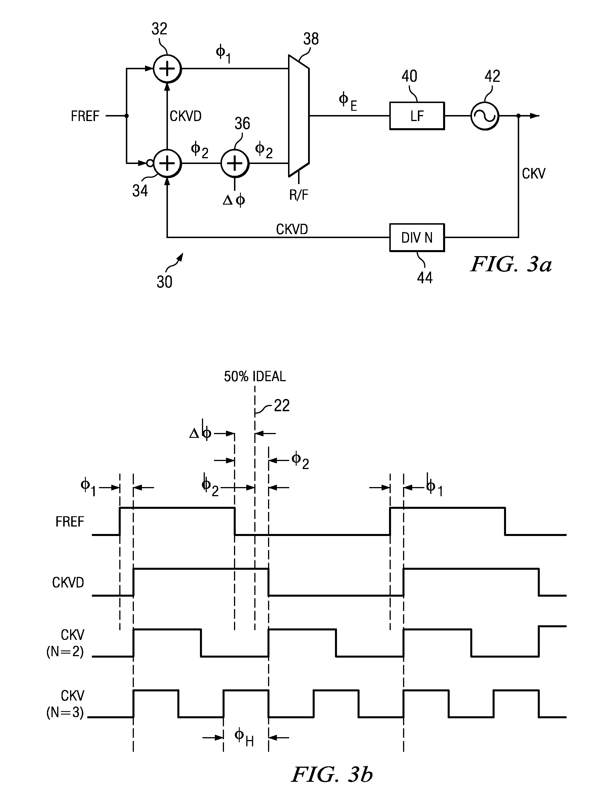
[0040]FIG. 3a illustrates the invention for using both edges of a reference clock in a PLL 30. FREF is input to a first phase detector 32 (which compares phase information on a first active edge, e.g. rising edge) of FREF and a second phase detector 34 (which compares phase information on a second active edge, e.g. falling edge) of FREF. Alternatively, the FREF signal is input to the first phase detector 32 and the inverted FREF signal is input to the second phase detector 34, and both phase detectors operate internally on the same active edge of the reference clock signals that are 180 degrees out of phase. The output of the first phase detector 32 is a first error signal φ1 and the output of the second phase detector 34 is a second intermediate error signal φ2′. The intermediate error signal φ2′ is added to Δφ through phase offset adder 36 to generate the second error signal φ2. The first and second error signals are input to multiplexer 38, which selects one of the first and seco...

second embodiment

[0042]It would also be possible to compare the edges of FREF with the output CKV. In this case, both the rising edge and falling edge of FREF would be compared to a rising edge of CKV, if N (fCKV / fFREF) was an even integer. If N is an odd integer, two approaches could be used. In the first approach, rising edges of FREF would be compared to rising edges of CKV and falling edges of FREF would be compared to falling edges of CKV (it would also be possible to compare rising edges of FREF to falling edges of CKV and vice-versa). In the second embodiment, a half-phase adjustment φH could be added to φ2′ along with Δφ by the phase offset adder 36, such that φ2=φ2′+Δφ+φH.

[0043]FIG. 4a illustrates a block diagram of an all digital PLL (ADPLL) 60 of the type disclosed in U.S. Ser. No. 10 / 008,462, now U.S. Pat. No. 7,006,589, to Staszewski et al, entitled “Frequency Synthesizer with. Phase Restart”, filed Nov. 30, 2001, which is incorporated by reference herein. This ADPLL is designed to work...


PUM


Abstract

A phase locked loop circuit (30, 100, 110) includes a controllable oscillator (42) for generating an output signal of desired frequency responsive to a control signal, a first phase detection circuit (32, 102, 112) for generating an output indicative of phase differential responsive to the output signal and a first edge of a reference signal and a second phase detection circuit (34, 104, 114) for generating an output indicative of phase differential responsive to the output signal and a second edge of a reference signal. The control signal to the controllable oscillator (42) is driven by the outputs of the first and second phase detections circuits.

Description

CROSS-REFERENCE TO RELATED APPLICATIONS[0001]This application claims the benefit of the filing date of copending provisional application U.S. Ser. No. 60 / 286,572, filed Apr. 25, 2001, entitled “Frequency Synthesizer Architecture of the Digital Radio Processor (v2.0)” to Staszewski et al.STATEMENT OF FEDERALLY SPONSORED RESEARCH OR DEVELOPMENT[0002]Not ApplicableBACKGROUND OF THE INVENTION[0003]1. Technical Field[0004]This invention relates in general to electronics and, more particularly, to a digital phase locked loop.[0005]2. Description of the Related Art[0006]A great reduction of the transistor features in recently developed deep-submicron CMOS processes shifts the design paradigm towards more digitally-intensive techniques. In a monolithic implementation, the manufacturing cost of a design is measured not in terms of a number of devices used but rather in terms of the occupied silicon area, no matter what the actual circuit complexity.[0007]Analog and RF circuits used in commun...

Claims


Application Information

Patent Timeline
Patent Type & Authority Patents(United States)
IPC IPC(8): H03D1/00H04L27/06H03C3/09H03K19/00H03L7/085H03L7/087H03L7/091H03L7/093H03L7/099H03L7/16
CPCH03C3/0966H03K19/0016H03L7/085H03L7/087H03L7/091H03L7/093H03L7/0991H03L7/16H03L7/08H04L7/0331H03L7/099H03L2207/50H04L7/0029H03L7/0992
Inventor STASZEWSKI, ROBERT B.LEIPOLD, DIRK
Owner TEXAS INSTR INC
Why Eureka
Try Eureka