
Buried gate transistor

a transistor and gate technology, applied in the field of buried gate transistors, can solve the problems of reducing device size, mos transistors with sub-micron scale to overcome many technical challenges, and short channel effects that are difficult to overcome, so as to improve the immunity to sces and increase junction overlap

Active Publication Date: 2012-12-25
INFINEON TECH AG
View PDF83 Cites 13 Cited by
  • Summary
  • Abstract
  • Description
  • Claims
  • Application Information

AI Technical Summary

Benefits of technology

This approach enhances the immunity to SCEs, increases junction overlap, and improves on-state current performance by maintaining high carrier concentration at the source / drain-channel contact, thereby optimizing transistor performance.

Problems solved by technology

However, with the continued reduction in device size, sub-micron scale MOS transistors have to overcome many technical challenges.
As the MOS transistors become smaller and their channel length decreases, problematic short channel effects (SCEs), such as, source to drain leakage become more pronounced.
However, effectively forming recessed gate transistors has been a difficult task.
However, the reduction of this overlap region (measured by overlap capacitance, Cov) greatly increases the resistance at that point, thereby reducing the on-state current (Ion) and performance of the device.
With conventional surface-gates in advanced devices, achieving good SCEs degrades the Ion due to this lack of overlap.

Method used


Image

  • Buried gate transistor
  • Buried gate transistor
  • Buried gate transistor

Examples


Embodiment Construction

[0023]The making and using of the presently preferred embodiments are discussed in detail below. It should be appreciated, however, that the present invention provides many applicable inventive concepts that may be embodied in a wide variety of specific contexts, which are not to be limited to the exemplary embodiments provided herein.

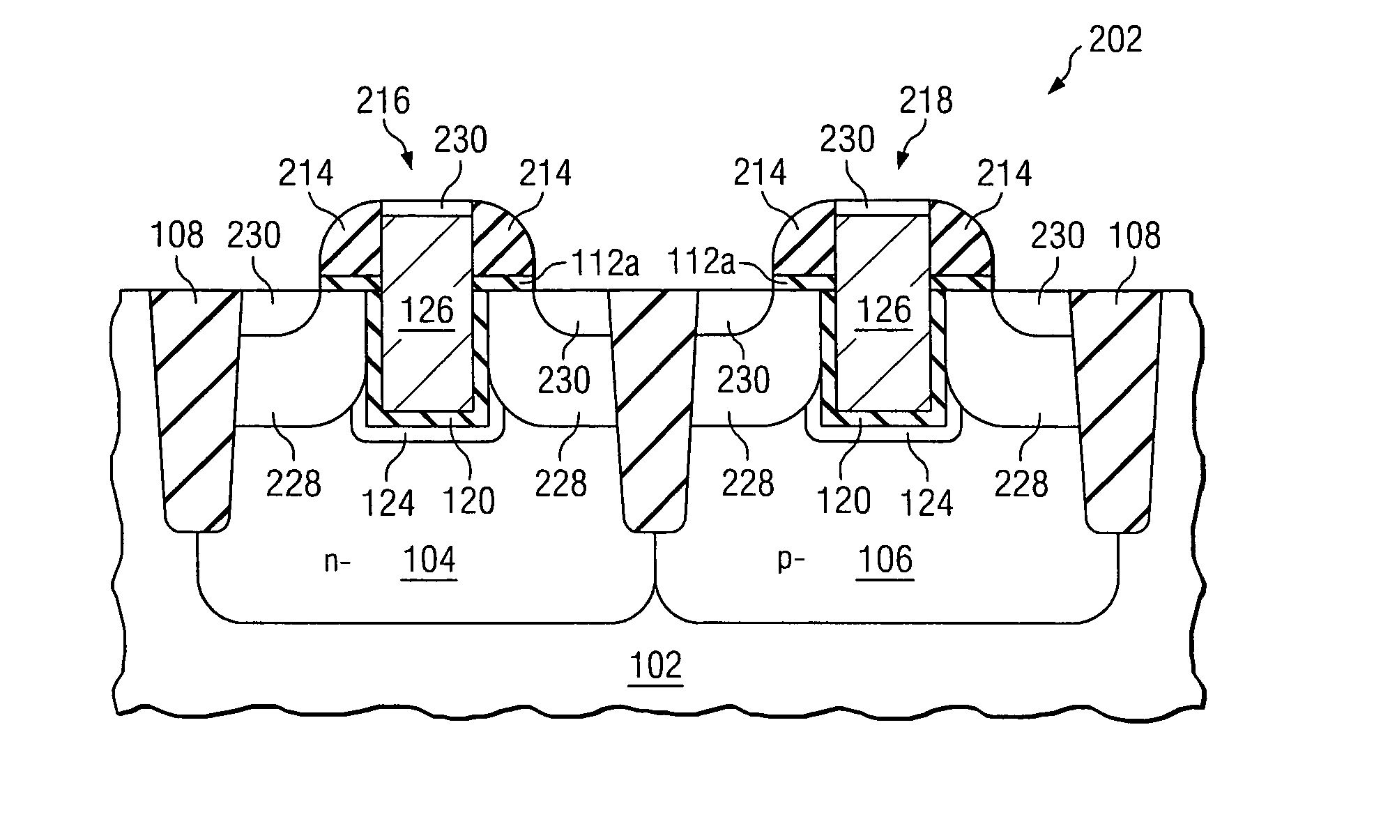
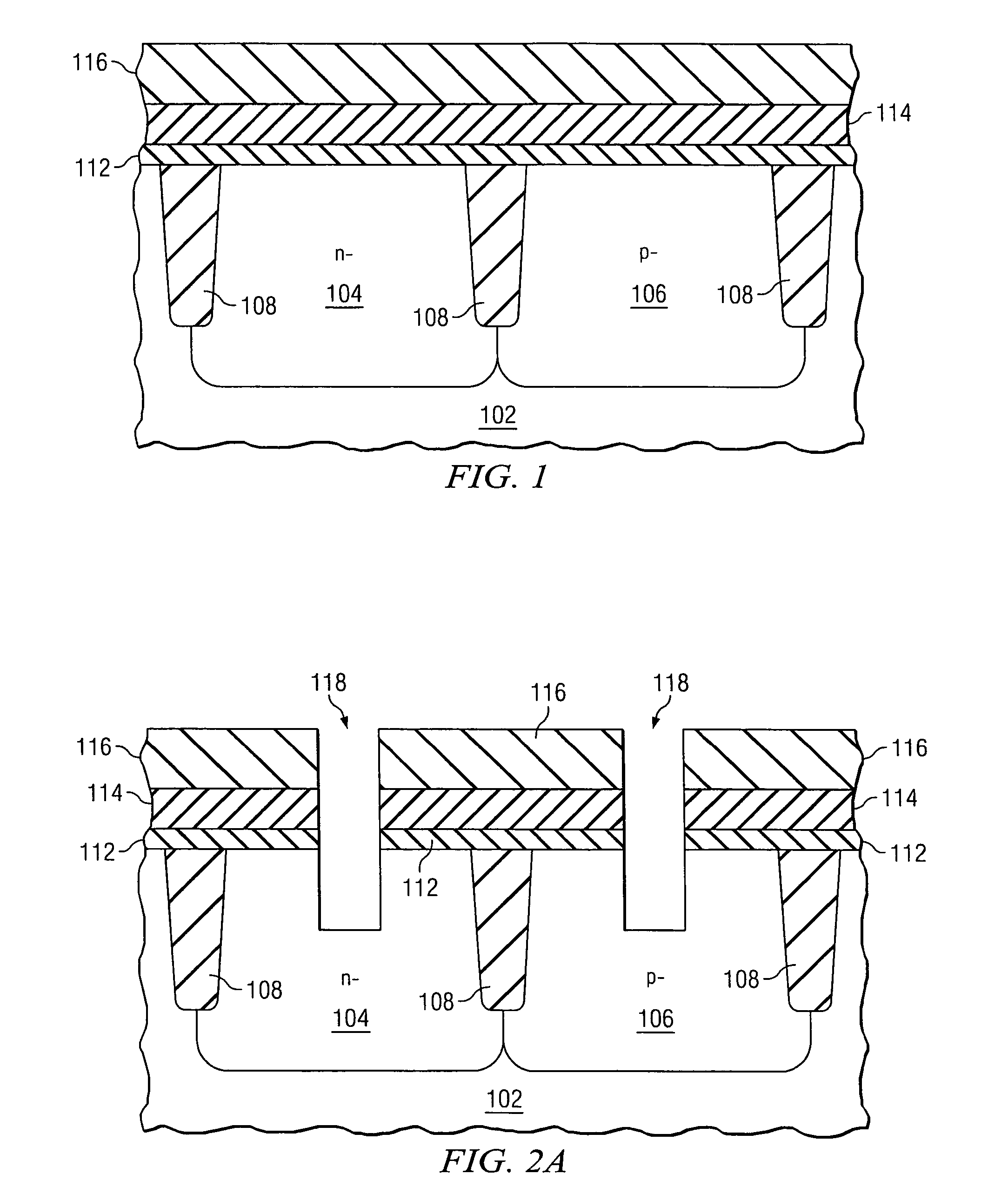
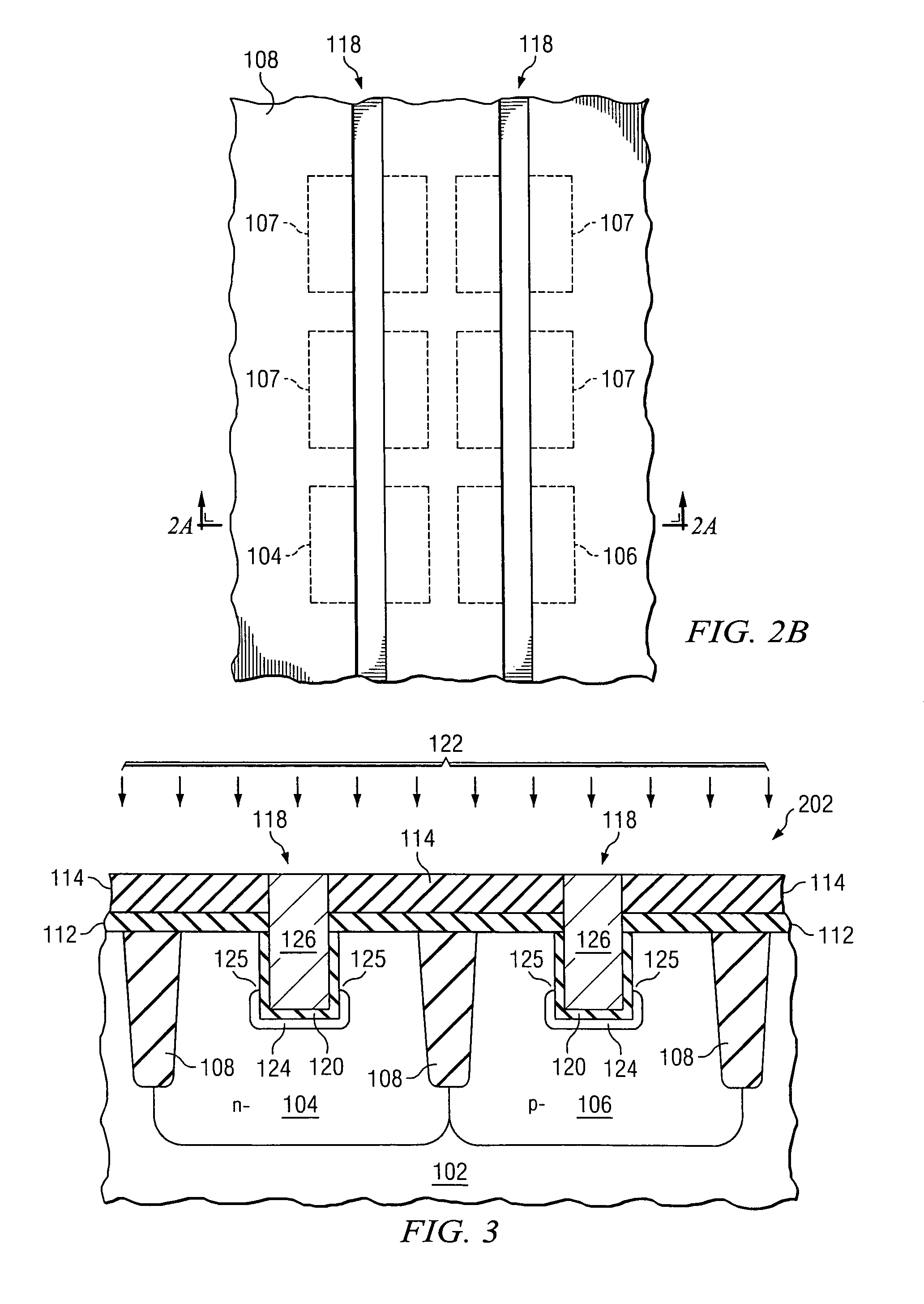
[0024]Embodiments of the invention provide an enabling process flow for simultaneous improvement in short channel effects such as Cov and Ioff. Such a process flow provides several advantages over the prior art. For example, embodiments of the invention include etching of isolation regions to allow a buried gate connecting multiple source / drains or for contacting poly on isolation. This provides multiple benefits, which include less topography problems, simpler process flow (only one CMP), less STI recess variation thereby causing less stress and threshold voltage (Vt) variation issues. Embodiments of the invention, also include performing source / drain...


PUM


Abstract

An embodiment of the invention provides a semiconductor fabrication method. The method comprises forming an isolation region between a first and a second region in a substrate, forming a recess in the substrate surface, and lining the recess with a uniform oxide. Embodiments further include doping a channel region under the bottom recess surface in the first and second regions and depositing a gate electrode material in the recess. Preferred embodiments include forming source / drain regions adjacent the channel region in the first and second regions, preferably after the step of depositing the gate electrode material. Another embodiment of the invention provides a semiconductor device comprising a recess in a surface of the first and second active regions and in the isolation region, and a dielectric layer having a uniform thickness lining the recess.

Description

TECHNICAL FIELD[0001]This invention relates generally to semiconductor device manufacturing and more particularly to a buried gate transistor for use in a semiconductor device.BACKGROUND[0002]Integrated circuits, such as ultra-large scale integrated (ULSI) circuits, can include as many as one billion transistors or more. Most typically, ULSI circuits are formed of Field Effect Transistors (FETs) formed in a Complementary Metal Oxide Semiconductor (CMOS) process. Each MOSFET includes a gate electrode formed over a channel region of the semiconductor substrate, which runs between a drain region and source region.[0003]To increase the device density and operation speed of the integrated circuits, the feature size of transistor within the circuits must be reduced. However, with the continued reduction in device size, sub-micron scale MOS transistors have to overcome many technical challenges. As the MOS transistors become smaller and their channel length decreases, problematic short cha...

Claims


Application Information

Patent Timeline
Patent Type & Authority Patents(United States)
IPC IPC(8): H01L29/66H10B12/00
CPCH01L21/26586H01L21/823807H01L21/823828H01L21/823885H01L27/10876H01L29/1083H01L29/6659H01L29/66621H01L29/42356H01L29/66613H01L21/28097H01L29/66575H01L21/28194H01L29/495H01L29/4966H01L29/517H01L29/518H01L29/665H01L27/088H01L29/66636H01L29/1041H01L29/7834H10B12/053
Inventor LINDSAY, RICHARDHIERLEMANN, MATTHIAS
Owner INFINEON TECH AG
Learn More