
Reactor control method

a technology of reactor control and control method, applied in the direction of hydrogen, combination devices, metal/metal-oxide/metal-hydroxide catalysts, etc., can solve the problems of increasing flow disparities, reducing the formation of coke, and reducing the cpox of distillate fuel

Active Publication Date: 2012-12-25
PRECISION COMBUSTION
View PDF19 Cites 14 Cited by
  • Summary
  • Abstract
  • Description
  • Claims
  • Application Information

AI Technical Summary

Benefits of technology

The present invention relates to a method for controlling the operating temperature of a reactor used for chemical reactions, particularly for the catalytic partial oxidation of liquid distillate fuels. The invention provides a closed-loop system for controlling the reactor input and other operating parameters to maintain the desired operating temperature. The method addresses the challenges of high temperature and coking, which can damage the catalyst and limit the duration of operation. The invention also addresses the need for a second closed-loop system to increase the minimum operating temperature of the reactor, which is important for achieving high selectivity to the desired products. The method can be applied to a variety of catalytic reactors and fuel types.

Problems solved by technology

Waterless catalytic partial oxidation (hereinafter referred to as “CPOx”) of liquid distillate fuels, such as, for example, diesel and JP8, with near complete conversion to Carbon (C1) products is a challenging proposition.
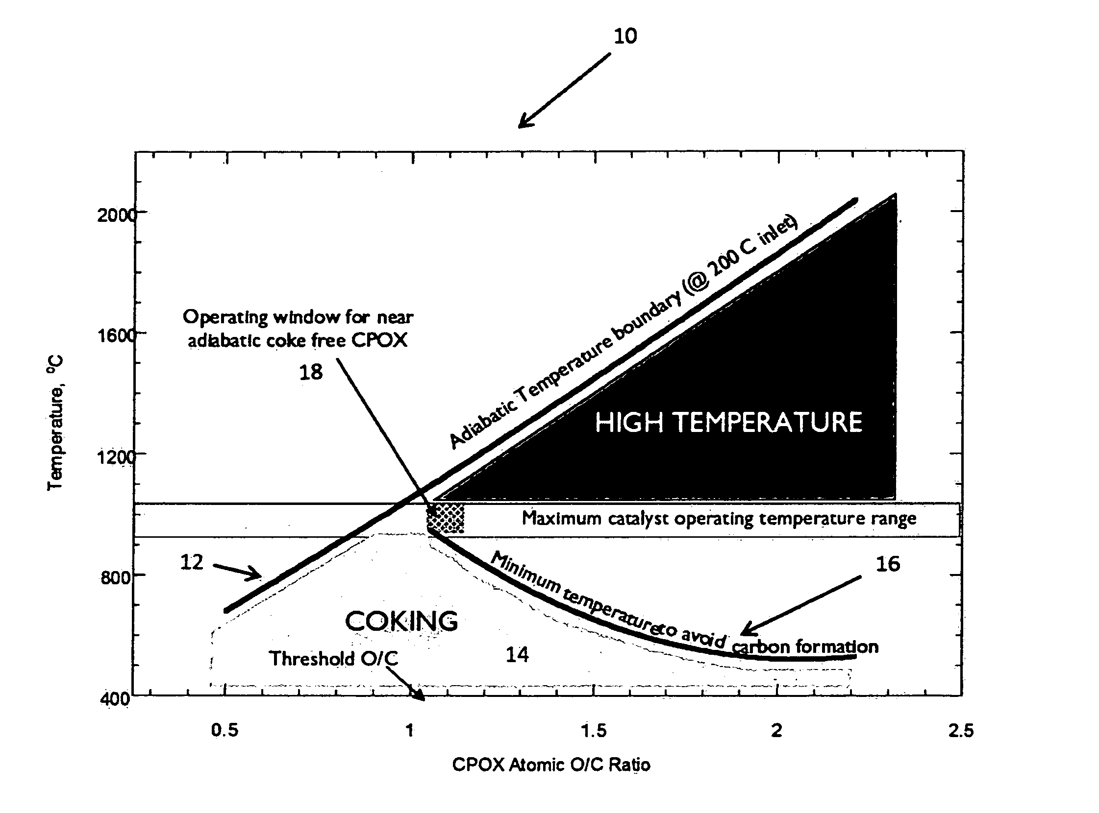
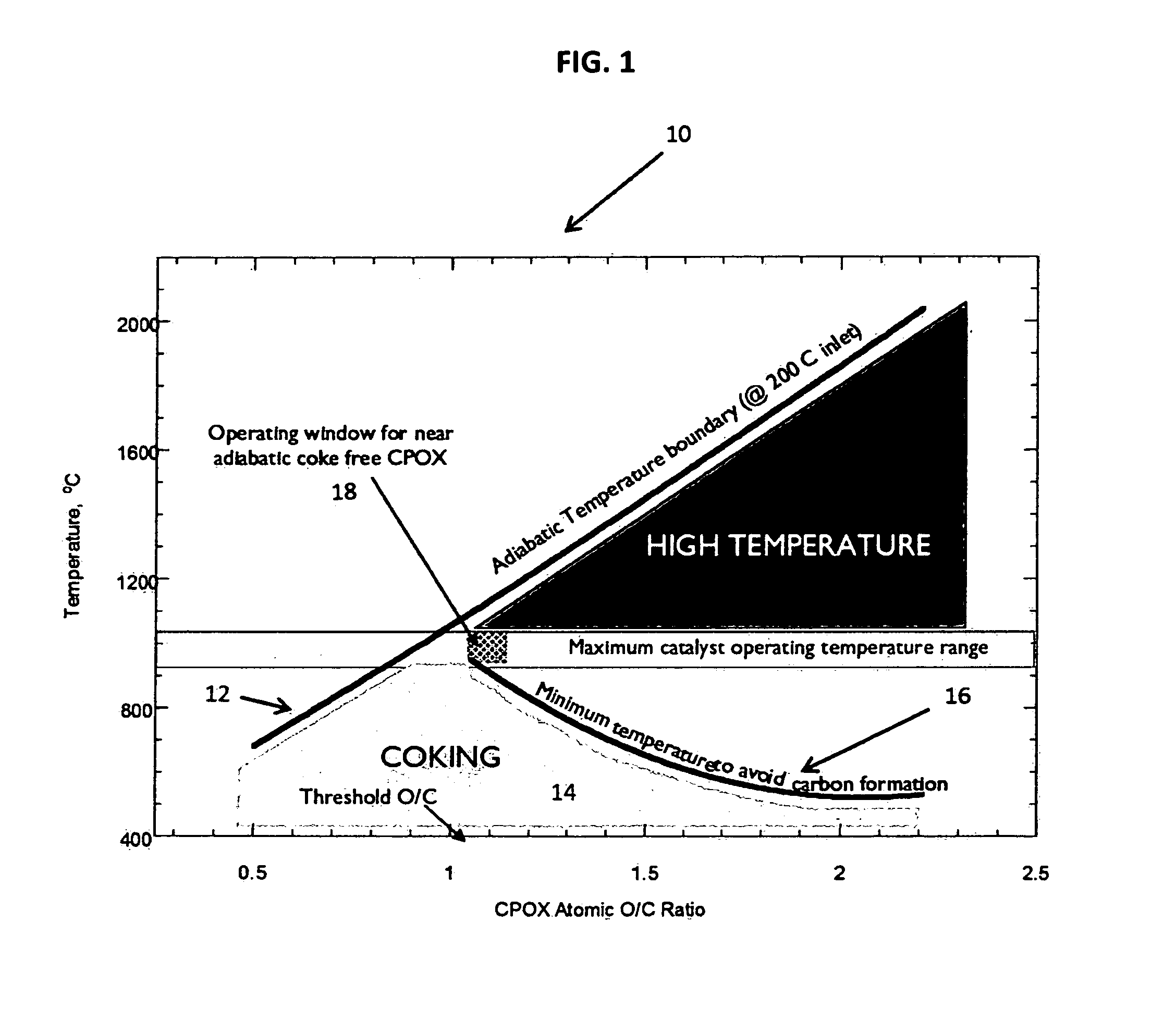
Moreover, CPOx of distillate fuel is made difficult due to carbon formation and / or excessively high reactor temperatures.
Due to the thermodynamic drive for coke formation, which can be exacerbated by inherent non-uniformities in the feed to a CPOx reactor, there is a need to diminish this coke formation and the subsequent catalyst temperature spread resulting from increasing flow disparities that arise.
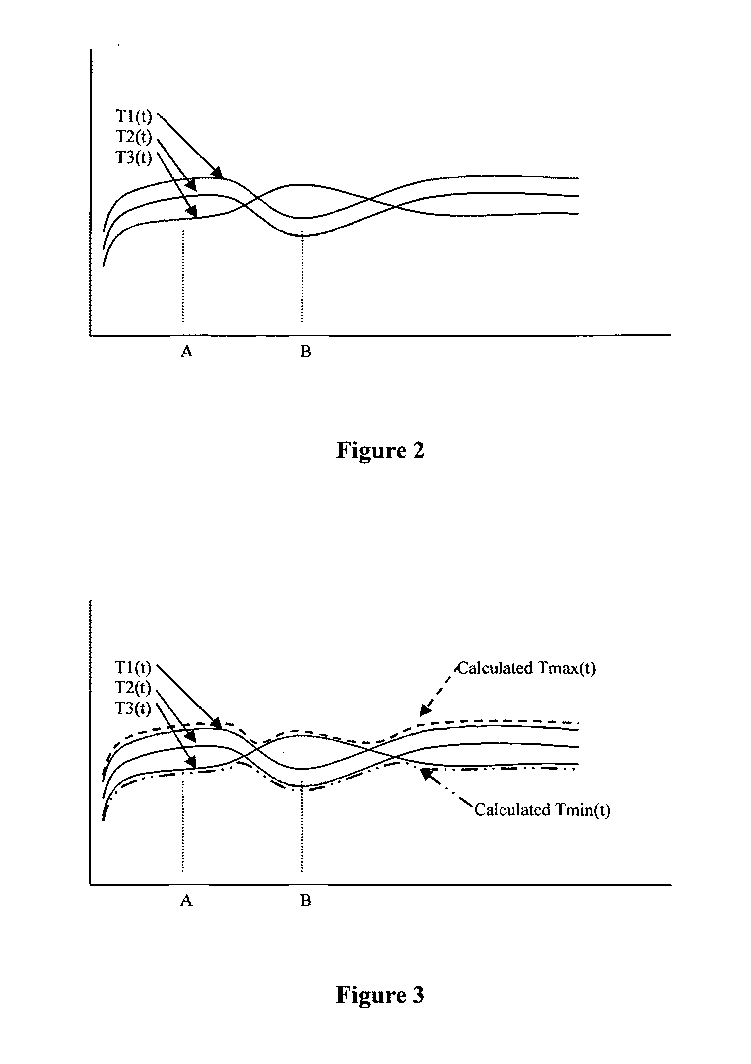
However, under coking and / or suboptimal mixing / fuel-atomization / vaporization conditions, having a maximum operating temperature within the reactor (hereinafter “Tmax”) set such that the minimum operating temperature within the reactor (hereinafter, “Tmin”) is above the thermodynamic threshold for coking will only be useful for a short time; inherent cold zones may develop, dropping the Tmin even though Tmax is held constant.
In this case, attempting to increase Tmin at point in the reactor by adjusting the fuel input would have the undesirable effect of increasing Tmax at another point in the reactor.

Method used


Image

  • Reactor control method
  • Reactor control method
  • Reactor control method

Examples


Embodiment Construction

[0008]A reforming reactor was tested for the dry reforming of distillate fuels. It was based on a small, modular catalytic reactor, which employed patented Microlith® substrate and catalyst technology available from Precision Combustion, Inc. in North Haven, Conn. High conversion of the diesel feed was observed with high selectivity of the hydrogen in the fuel converted to H2. A control algorithm was developed for stable long-term operation.

BRIEF DESCRIPTION OF THE DRAWINGS

[0009]FIG. 1 provides a graphical depiction of coking and high temperature regions associated with CPOx of liquid distillate fuels and an illustration of the desired operating region in accordance with the present invention.

[0010]FIGS. 2 and 3 provide a graphical depiction of reactor operating temperature trigger points for intervention by a closed-loop system controller in accordance with the present invention.

DETAILED DESCRIPTION OF THE INVENTION

[0011]FIG. 1 below presents a graphical depiction (10) of the resul...


PUM

PropertyMeasurementUnit
temperatureaaaaaaaaaa
operating temperatureaaaaaaaaaa

Abstract

A method is provided for controlling the operating temperature of a catalytic reactor using a closed-loop system that provides for varying the reactor input and other operating parameters in order to maintain the operating temperature of the reactor at or near the initial setpoint temperature for operation of the reactor. In one example, maximum and minimum operating temperatures with a catalytic partial oxidation reactor are controlled, as well as maintaining control over the corresponding minimum required ratio of oxygen atoms to carbon atoms, such that the operating temperature within the reactor is maintained below the material limits but above threshold temperatures for coking.

Description

CROSS-REFERENCE[0001]This application claims the benefit of U.S. Provisional Application No. 61 / 063,952 filed Feb. 7, 2008.FIELD OF THE INVENTION[0002]The present invention relates to a method for controlling the operating temperature of a catalytic reactor. While this is applicable to different types of catalytic reforming reactors, it is described here with reference to a Catalytic Partial Oxidation Reactor since the constraints of high temperature and coking are most acute. The present invention provides a method for protecting the catalyst from temperature excursions, minimizing coking, compensating for suboptimal mixing at the feed, recovering from operation under coking regimes, and providing for a much longer run-time duration at maximum operating temperature, and periodically or actively maintaining the minimum operating temperature.BACKGROUND OF THE INVENTIONBrief Description of the Related Art[0003]There are many methods known in the art for controlling the operating tempe...

Claims


Application Information

Patent Timeline
Patent Type & Authority Patents(United States)
IPC IPC(8): G05B13/00
CPCC10J3/723G05D23/1931C01B3/26Y10T436/218C10J2200/06Y10T436/207497
Inventor ROYCHOUDHURY, SUBIRDESJARDINS, JOEL M.SPENCE, DAVIDMASTANDUNO, RICHARDWALSH, DENNIS E.PFEFFERLE, WILLIAM C.
Owner PRECISION COMBUSTION
Learn More