
Perpendicular magnetic recording medium

a magnetic recording medium and perpendicular technology, applied in the field of perpendicular magnetic recording medium, can solve the problems of more significant thermal fluctuation, failure to stabilize the retention of recorded signals, and “thermal fluctuation” has become a problem, so as to improve the performance of noise characteristic, s/n characteristic, and other characteristics

Active Publication Date: 2012-12-11
FUJI ELECTRIC CO LTD
View PDF12 Cites 4 Cited by
  • Summary
  • Abstract
  • Description
  • Claims
  • Application Information

AI Technical Summary

Benefits of technology

This approach improves thermal stability and recordability, along with noise and signal-to-noise characteristics, allowing for higher recording density without degrading performance.

Problems solved by technology

As a result of this remarkable enhancement of the recording density, “thermal fluctuation” has become a problem.
The thermal fluctuation phenomenon causes failure of stable retention of recorded signals.
In the longitudinal magnetic recording system commonly employed now, the higher recording density causes more significant thermal fluctuation.
Therefore, a perpendicular magnetic recording medium still raises a problem of thermal fluctuation.
If the increase of the magnetic field intensity is significant, recording may become impossible.
However, both of these tend to lower the easiness with which a magnetic recording medium is recorded, referred to as “recordability.”
Therefore, the recordability inevitably deteriorates in the magnetic recording medium in this method.
It has been disclosed, however, that the use of antiferromagnetically coupled magnetic recording layers causes an increase of the switching field.
Thus, degradation of the recordability is essentially inevitable.
The decrease of a magnetization reversal unit, however, degrades thermal stability as described above, and also increases the switching field of the magnetic recording medium due to a decrease of the demagnetizing magnetic field.
This circumstance has been an obstacle to advancing high density recording of a magnetic recording medium.

Method used


Image

  • Perpendicular magnetic recording medium
  • Perpendicular magnetic recording medium
  • Perpendicular magnetic recording medium

Examples


example 1

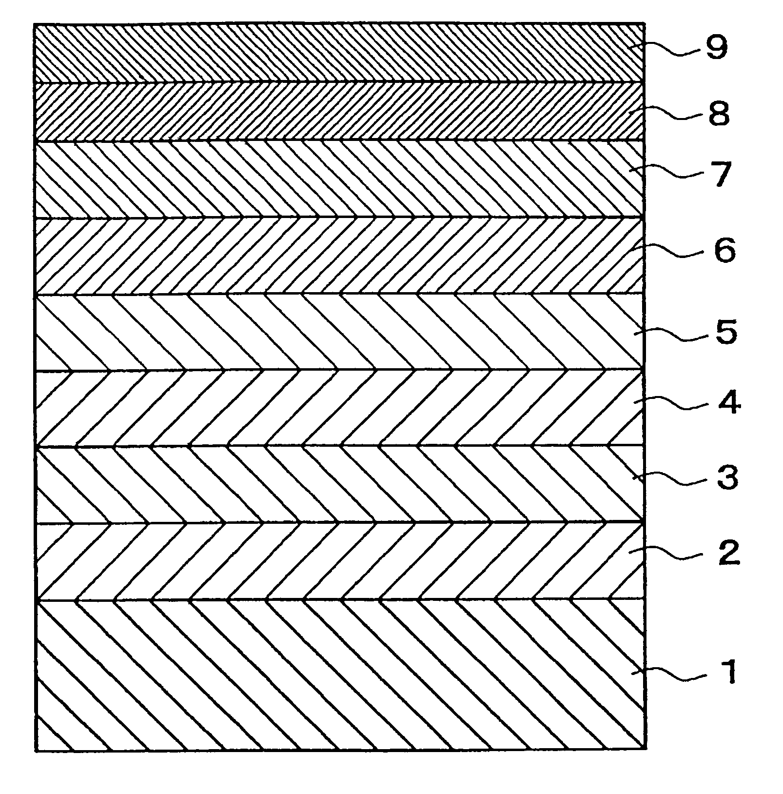
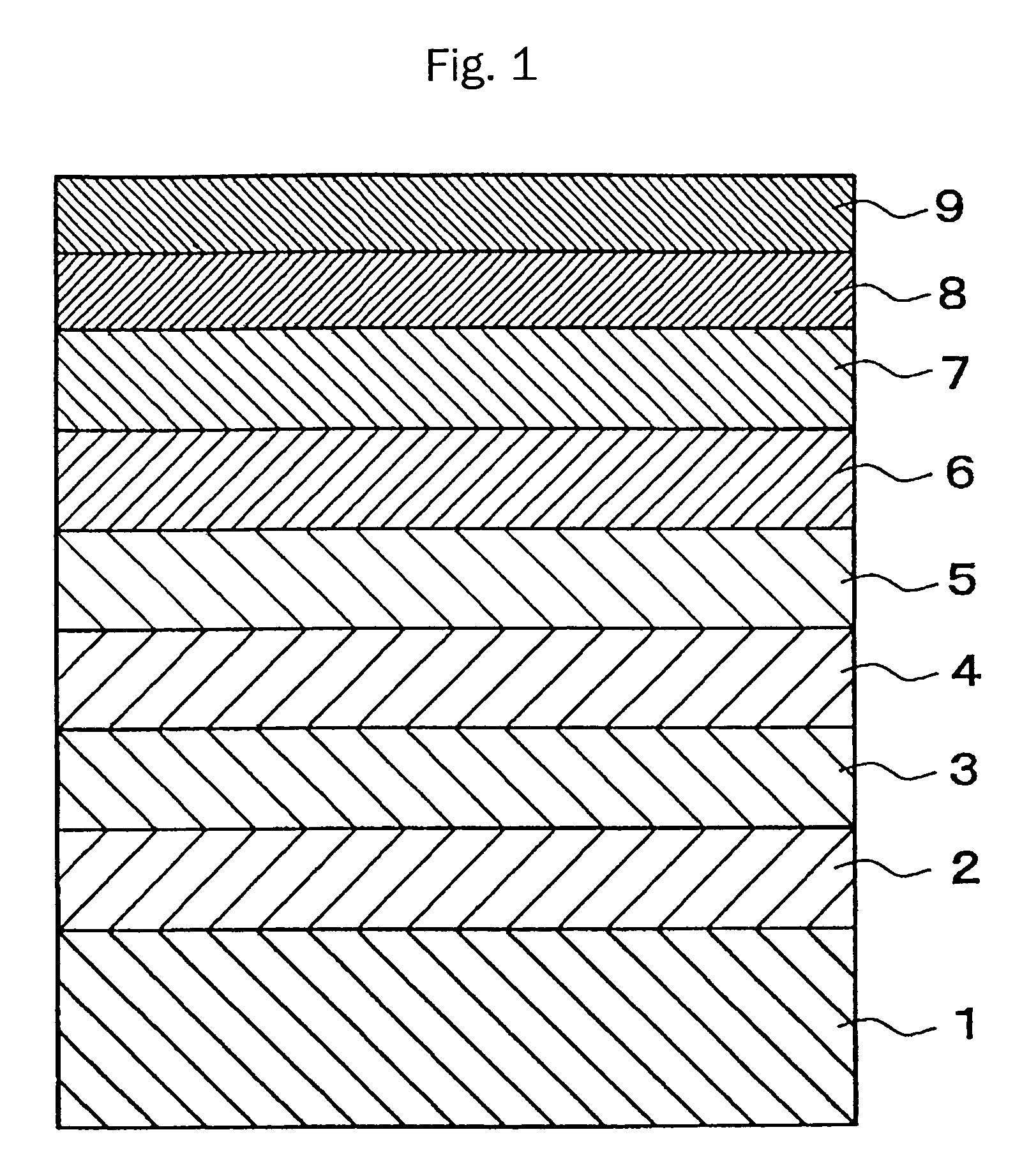
[0066]An example is described on a perpendicular magnetic recording medium manufactured with a structure shown in FIG. 1. Nonmagnetic substrate 1 used was a chemically strengthened glass substrate having a smooth surface (N-5 glass substrate manufactured by HOYA Corporation). After cleaning, the substrate was introduced into a sputtering apparatus and amorphous soft magnetic backing layer 2 of CoZrNb having a thickness of 200 nm was deposited using a target of 87 at % Co-5 at % Zr-8 at % Nb. Then, underlayer 3 of NiFeSi having a thickness of 11 nm was deposited using a target of a Permalloy, 82 at % Ni-12 at % Fe-6 at % Si. Subsequently, nonmagnetic intermediate layer 4 of ruthenium having a thickness of 10 nm was deposited using a target of ruthenium under an argon gas pressure of 4.0 Pa. Subsequently, first magnetic recording layer 5 of CoCrPt—SiO2 having a granular structure and a thickness of 10 nm was deposited using a target of 90 mol % (74 at % Co-12 at % Cr-14 at % Pt)—10 mo...

example 2

[0081]A perpendicular magnetic recording medium having a structure shown in FIG. 1 was produced with varied materials for the magnetic recording layers and for the coupling layer. Nonmagnetic substrate 1 was a chemically strengthened glass substrate having a smooth surface (N-5 glass substrate manufactured by HOYA Corporation). After cleaning, the substrate was introduced into a sputtering apparatus and amorphous soft magnetic backing layer 2 of CoZrNb having a thickness of 200 nm was deposited using a target of 87 at % Co-5 at % Zr-8 at % Nb. Then, underlayer 3 of NiFeSi having a thickness of 11 nm was deposited using a target of Permalloy, 82 at % Ni-12 at % Fe-6 at % Si. Subsequently, nonmagnetic intermediate layer 4 of ruthenium having a thickness of 10 nm was deposited using a target of ruthenium under argon gas pressure of 4.0 Pa. Subsequently, first magnetic recording layer 5 of CoCrPt—SiO2 having a granular structure and a thickness of 10 nm was deposited using a target of 9...

example 3

[0087]A perpendicular magnetic recording medium having a structure of FIG. 1 was manufactured.

[0088]Nonmagnetic substrate 1 was a chemically strengthened glass substrate having a smooth surface (N-5 glass substrate manufactured by HOYA Corporation). After cleaning, the substrate was introduced into a sputtering apparatus and amorphous soft magnetic backing layer 2 of CoZrNb having a thickness of 200 nm was deposited using a target of 87 at % Co-5 at % Zr-8 at % Nb. Then, an underlayer 3 of NiFeSi having a thickness of 11 nm was deposited using a target of a Permalloy, 82 at % Ni-12 at % Fe-6 at % Si. Subsequently, nonmagnetic intermediate layer 4 of ruthenium having a thickness of 10 nm was deposited using a target of ruthenium under argon gas pressure of 4.0 Pa, and then first magnetic recording layer 5 of CoCrPt—SiO2 having a granular structure and a thickness of 9.5 nm was deposited using a target of 90 mol % (72 at % Co-10 at % Cr-18 at % Pt)—10 mol % SiO2 under a gas pressure o...


PUM

PropertyMeasurementUnit
thicknessaaaaaaaaaa
thicknessaaaaaaaaaa
temperatureaaaaaaaaaa

Abstract

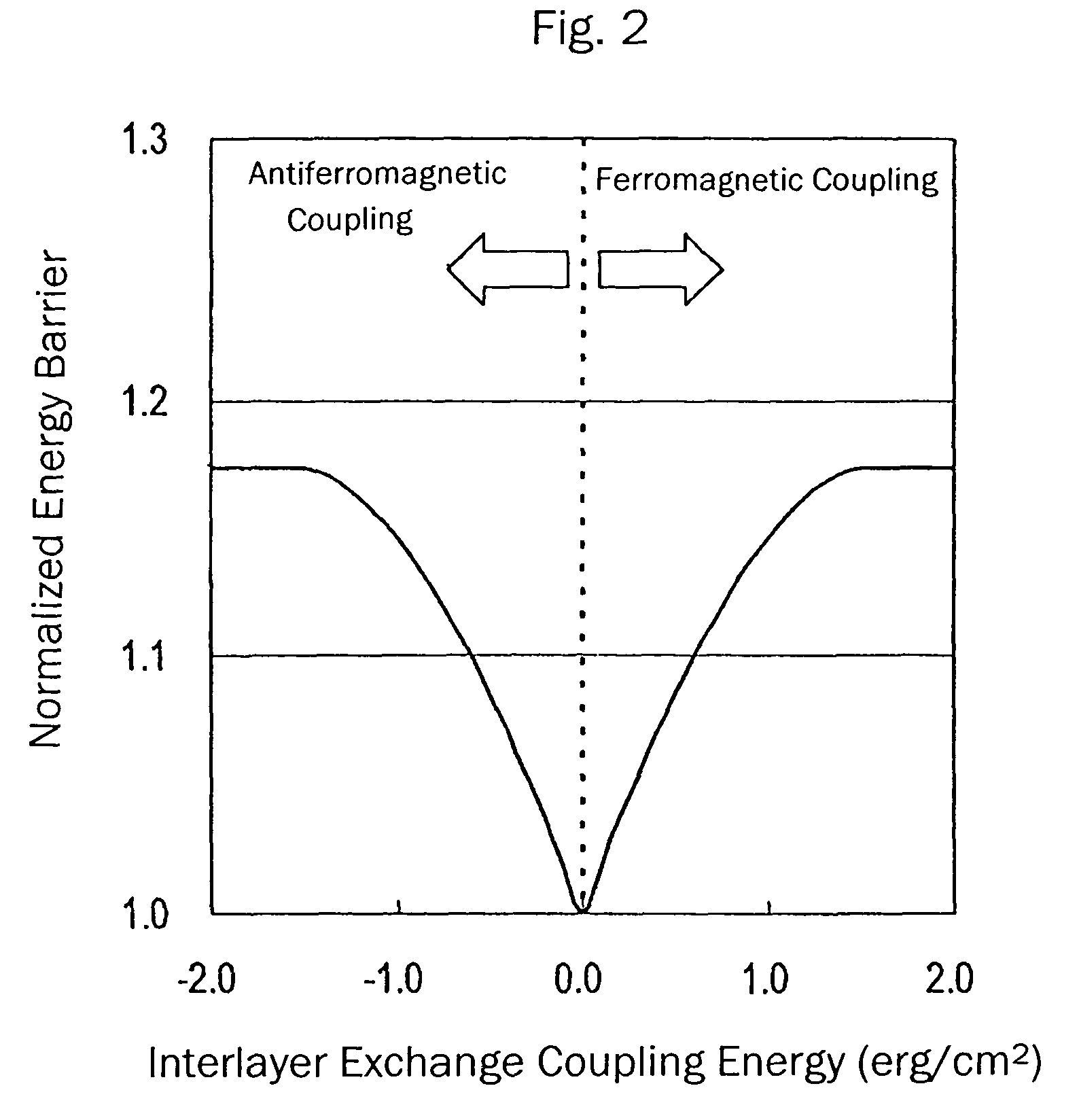
A perpendicular magnetic recording medium is disclosed that achieves improved recordability without deteriorating thermal stability by reducing the switching field. A perpendicular magnetic recording medium of the invention has a first magnetic recording layer and a second magnetic recording layer between with is interposed a coupling layer that ferromagnetically couples the two layers. The first and second magnetic recording layers satisfy an inequality Ku1T1>Ku2T2 in the case where Hk1 >Hk2 and an inequality Ku1T1<Ku2T2 in the case where Hk1<Hk2, where Hk1 and Hk2 are anisotropy magnetic fields, Ku1 and Ku2 are uniaxial anisotropy constants, and T1 and T2 are thicknesses of the first magnetic recording layer and the second recording layer, respectively. An exchange coupling energy between the magnetic recording layers is preferably at least 5×10⁻³ erg / cm2. Advantageously, the coupling layer is mainly composed of a material selected from V, Cr, Fe, Co, Ni, Cu, Nb, Mo, Ru, Rh, Ta, W, Re, and Ir, and has a thickness of at most 2 nm. At least one of the magnetic recording layers preferably has a granular structure.

Description

CROSS REFERENCE TO RELATED APPLICATIONS[0001]This application is based on, and claims priority to, Japanese Application No. 2004-197775, filed on Jul. 5, 2004, the contents of which are incorporated herein by reference.BACKGROUND OF THE INVENTION[0002]A. Field of the Invention[0003]The present invention relates to a perpendicular magnetic recording medium mounted on various magnetic recording devices, in particular to a perpendicular magnetic recording medium mounted on a hard disk drive used for an external storage device of computers, AV equipment, and other apparatus.[0004]B. Description of the Related Art[0005]The recording density of hard disk drives (HDDs) is rapidly increasing and this trend is likely to continue in the future. As a result of this remarkable enhancement of the recording density, “thermal fluctuation” has become a problem. The thermal fluctuation phenomenon causes failure of stable retention of recorded signals. In the longitudinal magnetic recording system co...

Claims


Application Information

Patent Timeline
Patent Type & Authority Patents(United States)
IPC IPC(8): G11B5/66
CPCG11B5/66G11B5/65G11B5/676
Inventor TAKENOIRI, SHUNJISAKAI, YASUSHI
Owner FUJI ELECTRIC CO LTD
Learn More