Reagent for analyzing urine and method for analyzing urine
a technology of reagents and urine, applied in the direction of material analysis through optical means, fluorescence/phosphorescence, instruments, etc., to achieve the effect of accurately distinguishing sperm among urine particles
- Summary
- Abstract
- Description
- Claims
- Application Information
AI Technical Summary
Benefits of technology
Problems solved by technology
Method used
Image

Examples
example 1
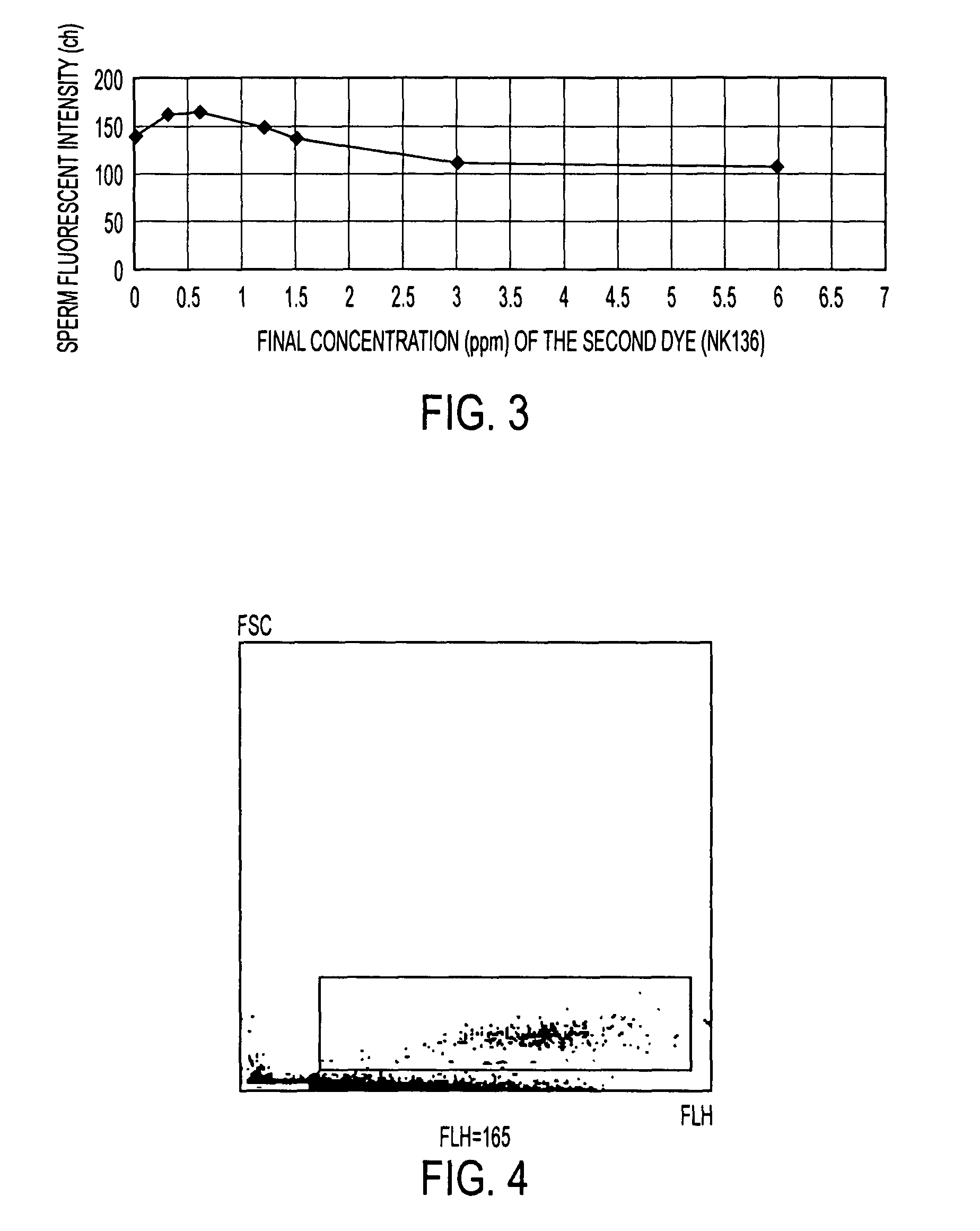
[0128]As a second reagent, the second reagent B prepared so that the final concentration of NK529 became 6 ppm, and the final concentration of NK136 became 0.6 ppm, was used.
[0129]The urine specimen 1 was mixed with the first reagent and, further, the mixture was mixed with the second reagent B to prepare a measuring sample from the urine specimen 1.
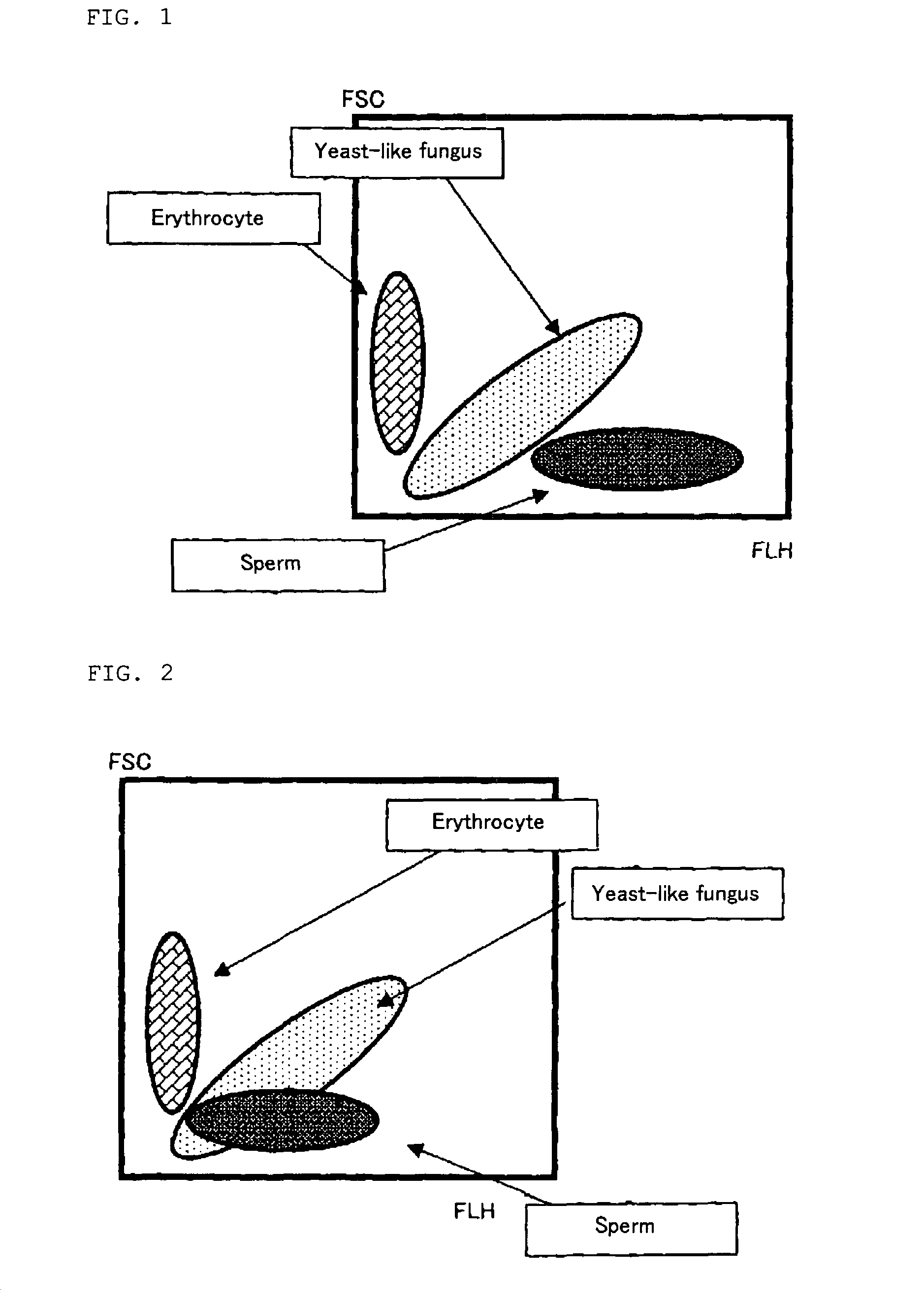
[0130]The prepared measuring sample was introduced into a flowcell, and a light intensity was measured with a flowcytometer to produce a two-dimensional scattering diagram using a fluorescent intensity (abscissa axis) and a forward scattered light intensity (ordinate axis) as two axes. The resulting scattering diagram is shown in FIG. 4. In addition, in the scattering diagram, a region thought that sperm appears (region surrounded with a solid line in a scattering diagram) was specified. An average of a fluorescent intensity detected from sperm appearing in the region was 165.
example 2
[0135]As a second reagent, the second reagent B prepared so that the final concentration of NK529 became 6 ppm, and the final concentration of NK136 became 0.6 ppm, was used.
[0136]The urine specimen 2 was mixed with the first reagent and, further, the mixture was mixed with the second reagent B to prepare a measuring sample from a urine specimen 2.
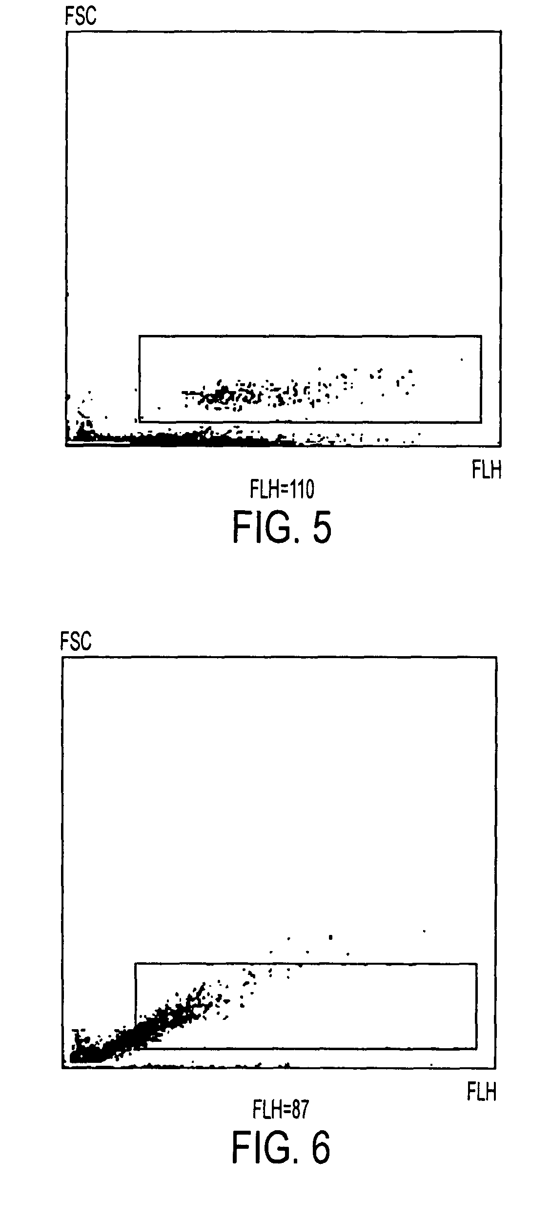
[0137]The prepared measuring sample was introduced into a flowcell, a light intensity was measured with a flowcytometer, and a two-dimensional scattering diagram using a fluorescent intensity (abscissa axis) and a forward scattered light intensity (ordinate axis) as two axes was produced. The resulting scattering diagram is shown in FIG. 6. In addition, in the scattering diagram, an average fluorescent intensity of a region thought that sperm appears (in the figure, a part surrounded with a solid line) was calculated, and found to be 87.
example 3
[0142]As a second reagent, the second reagent C prepared so that the final concentration of NK529 became 6 ppm, and the final concentration of NK2251 became 0.6 ppm, was used.
[0143]The urine specimen 3 was mixed with the first reagent and, further, the mixture was mixed with the second reagent C to prepare a measuring sample from the urine specimen 3.
[0144]The prepared measuring sample was introduced into a flowcell, a light intensity was measured with a flowcytometer, and a two-dimensional scattering diagram using a fluorescent intensity (abscissa axis) and a forward scattered light (ordinate axis) as two axes was produced. The resulting scattering diagram is shown in FIG. 8. In addition, in the scattering diagram, a region thought that sperm appears (region surrounded with a solid line in a scattering diagram) was specified. An average of a fluorescent intensity detected from sperm appearing in this region was 165.
PUM
| Property | Measurement | Unit |
|---|---|---|
| absorption wavelength | aaaaa | aaaaa |
| absorption wavelength | aaaaa | aaaaa |
| wavelength | aaaaa | aaaaa |
Abstract
Description
Claims
Application Information
 - R&D
- Intellectual Property
- Life Sciences
- Materials
- Tech Scout
- Unparalleled Data Quality
- Higher Quality Content
- 60% Fewer Hallucinations
Browse by: Latest US Patents, China's latest patents, Technical Efficacy Thesaurus, Application Domain, Technology Topic, Popular Technical Reports.
© 2025 PatSnap. All rights reserved.Legal|Privacy policy|Modern Slavery Act Transparency Statement|Sitemap|About US| Contact US: help@patsnap.com