Prosthetic joint assembly and joint member therefor

a joint and prosthetic technology, applied in the field of medical implants, can solve the problems of accelerated wear, tissue inflammation and harm, and implant damage, and achieve the effects of undesirable implant replacement, improved prosthetic performance, and improved prosthetic performan

Active Publication Date: 2012-11-13
BIOMEDFLEX
View PDF396 Cites 14 Cited by
  • Summary
  • Abstract
  • Description
  • Claims
  • Application Information

AI Technical Summary

Problems solved by technology

The problem with this type of configuration is the polymer eventually begins to degrade due to the caustic nature of blood, the high impact load, and high number of load cycles.
As the resilient member degrades, pieces of polymer may be liberated into the joint area, often causing accelerated wear, implant damage, and tissue inflammation and harm.
Implant replacement is undesirable from a cost, inconvenience, patient health, and resource consumption standpoint.
Implants using two hard elements of conventional design will be, however, subject to rapid wear.
First, a joint having one hard, rigid element on another will not be perfectly shaped to a nominal geometry.
Such imperfections will result in points of high stress, thus causing localized wear.
Furthermore, two hard elements would lack the resilient nature of a natural joint.
Some cyclical load in these areas stimulates bone growth and strength; however, excessive loads or shock stress or impulse loading the bone-to-implant interface will result in localized bone mass loss, inflammation, and reduced support.

Method used


Image

  • Prosthetic joint assembly and joint member therefor
  • Prosthetic joint assembly and joint member therefor
  • Prosthetic joint assembly and joint member therefor

Examples


Embodiment Construction

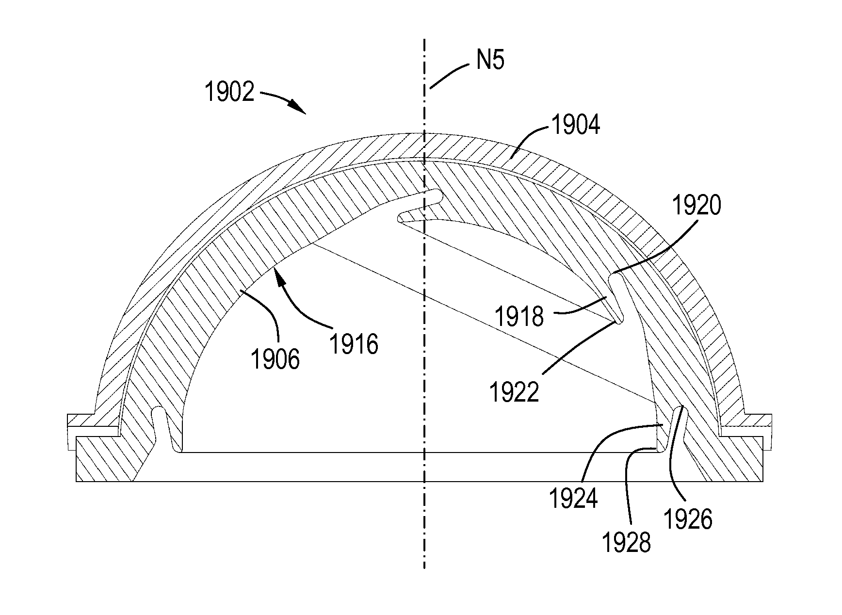
[0083]The present invention provides a specialized implant contact interface (implant geometry). In this geometry, an implanted joint includes two typically hard (i.e. metal or ceramic) members; however, at least one of the members is formed such that it has the characteristics of a resilient member, such as: the ability to absorb an impact load; the ability to absorb high cycle loading; the ability to be self cleaning; and the ability to function as a hydrodynamic and / or hydrostatic bearing.

[0084]Generally, the contact resilient member is flexible enough to allow elastic deformation and avoid localized load increases, but not so flexible as to risk plastic deformation, cracking and failure. In particular, the resilient member is designed such that the stress levels therein will be below the high-cycle fatigue endurance limit. As an example, the resilient member might be only about 10% to about 20% as stiff as a comparable solid member. It is also possible to construct the resilient...


PUM

PropertyMeasurementUnit
porosityaaaaaaaaaa
thicknessaaaaaaaaaa
diameteraaaaaaaaaa

Abstract

A prosthetic joint member includes: a generally concave cup with an outer surface that is bone-implantable, the cup including a first indexing feature; a concave insert disposed inside the cup, the insert comprising a rigid material and including a concave interior defining a nominal surface, the interior including a cantilevered flange defined by an undercut in the insert, the flange defining a wear-resistant first contact surface which protrudes inward relative to the nominal surface, the insert including a second indexing feature. The first and second indexing features engage each other so as to retain the insert in a fixed angular orientation relative to the cup.

Description

CROSS-REFERENCE TO RELATED APPLICATIONS[0001]This application is a Continuation-in-Part of application Ser. No. 13 / 311,119, filed Dec. 5, 2011, currently pending, which is a Continuation of application Ser. No. 13 / 073,963, filed Mar. 28, 2011, now U.S. Pat. No. 8,070,823, which is a Continuation-in-Part of application Ser. No. 12 / 826,620, filed Jun. 29, 2010, Now U.S. Pat. No. 7,914,580, which is a Continuation-in-Part of application Ser. No. 12 / 714,288, filed Feb. 26, 2010, now U.S. Pat. No. 7,905,919, which is a Continuation-in-Part of application Ser. No. 11 / 936,601, filed Nov. 7, 2007, currently pending, which claims the benefit of Provisional Patent Application 60 / 864,667, filed Nov. 7, 2006.BACKGROUND OF THE INVENTION[0002]This invention relates generally to medical implants, and more particularly to prosthetic joints having conformal geometries and wear resistant properties.[0003]Medical implants, such as knee, hip, and spine orthopedic replacement joints and other joints and...

Claims


Application Information

Patent Timeline
Patent Type & Authority Patents(United States)
IPC IPC(8): A61F2/30A61F2/32
CPCA61F2/30767C23C30/00A61F2/34A61F2/4425A61F2/32A61F2/36A61F2/3603A61F2/367A61F2/3676A61F2/38A61F2002/30014A61F2002/30112A61F2002/30153A61F2002/30322A61F2002/30324A61F2002/305A61F2002/30563A61F2002/30565A61F2002/30571A61F2002/30589A61F2002/3066A61F2002/30673A61F2002/30675A61F2002/30682A61F2002/30878A61F2002/3092A61F2002/30922A61F2002/30929A61F2002/30934A61F2002/30937A61F2002/30955A61F2002/30968A61F2002/30981A61F2002/3438A61F2002/3446A61F2002/3451A61F2002/3495A61F2002/3611A61F2002/3895A61F2002/443A61F2230/0004A61F2230/0019A61F2250/0018A61F2250/0026A61F2250/0036A61F2310/00011A61F2310/00179A61F2310/00239A61F2310/0058A61F2/3094A61F2002/3054A61F2002/30593
Inventor KELLAR, FRANZ W.CROWDER, JR., HAROLD LLOYDDUQUETTE, SCOTT M.
Owner BIOMEDFLEX
Why Eureka
Try Eureka