
Automatic verification of device models

a technology of automatic verification and device model, applied in the field of automatic verification of device model, can solve the problems of insufficient code coverage of test files created by conventional methods, high cost, and inability to meet the requirements of the test, and achieve the effects of less skill and experience, less cost, and more rapid creation

Active Publication Date: 2012-09-18
NVIDIA CORP
View PDF74 Cites 6 Cited by
  • Summary
  • Abstract
  • Description
  • Claims
  • Application Information

AI Technical Summary

Benefits of technology

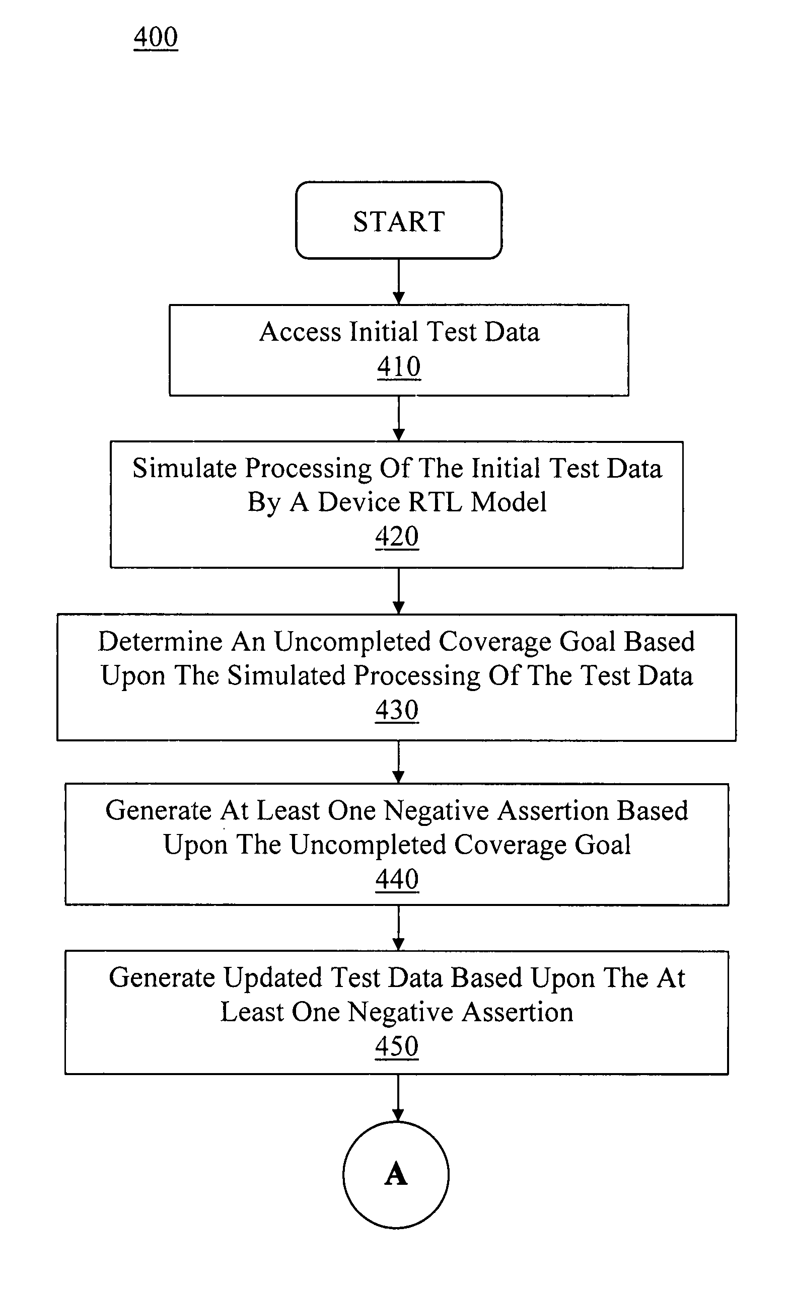
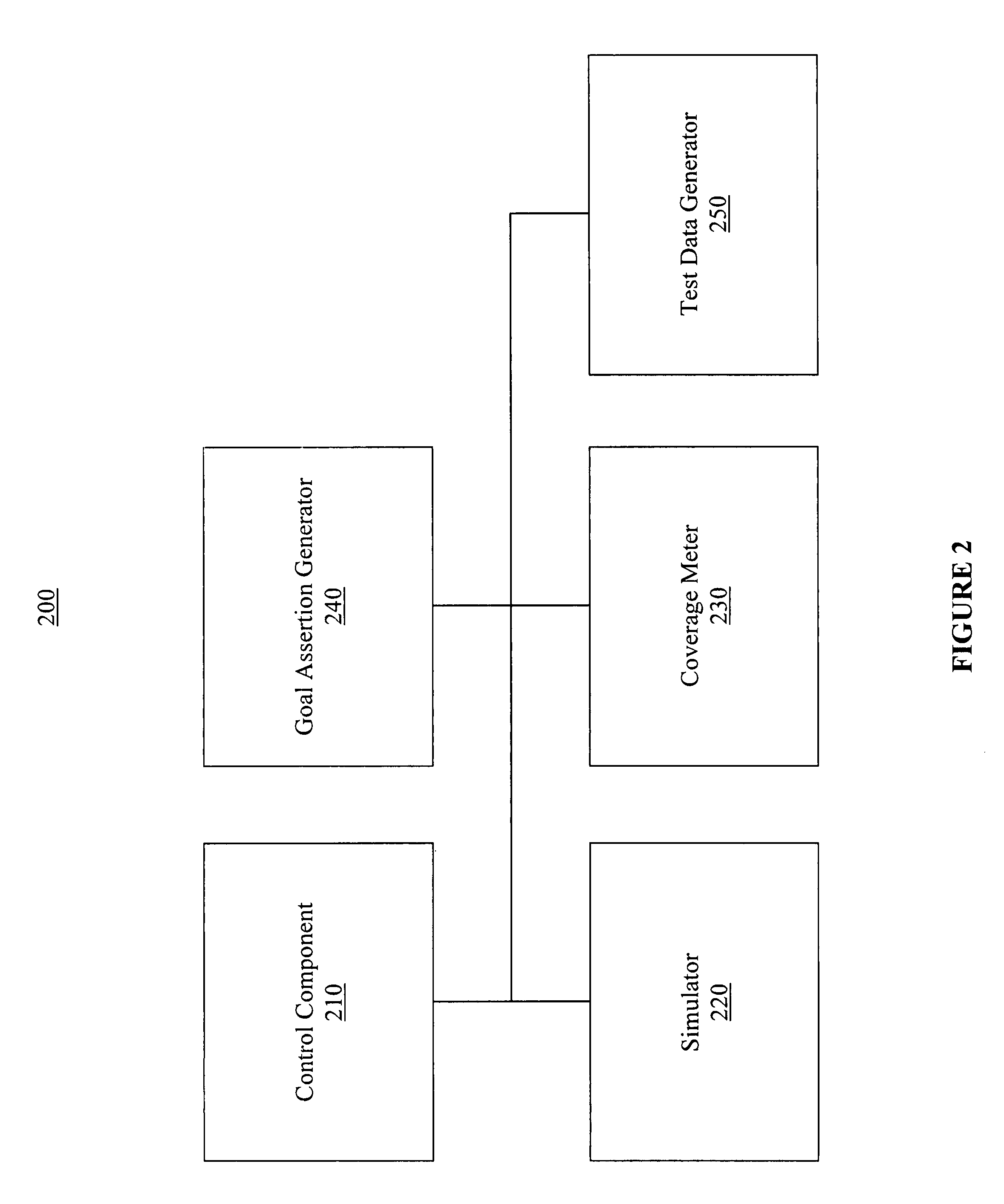
The present invention provides a solution for generating test files for automatic verification of a device model. The invention allows for faster and less expensive creation of test files, with less skill and experience required. The test data generator automatically generates test files based on uncompleted coverage goals, which can be expressed as negative assertions. The test files can be applied to a device RTL model or a device reference model for comparison and verification of the device model. The invention also allows for the automatic generation of functional coverage goals and the creation of test files to complete the coverage goals. Overall, the invention provides an efficient and cost-effective mechanism for generating test files for automatic verification of a device model.

Problems solved by technology

As such, conventional methods for creating test files are very time consuming and costly.
Additionally, test files created by conventional methods often provide inadequate code coverage given the extensive skill and experience required to create an acceptable test file using conventional methods of generating test files.
Further, inadequate functional coverage is common with conventional methods of generating test files since the design or verification engineer must not only specify functional coverage goals which requires skill and experience, but also write a test file which covers the specified goals.

Method used


Image

  • Automatic verification of device models
  • Automatic verification of device models
  • Automatic verification of device models

Examples


Embodiment Construction

[0023]Reference will now be made in detail to embodiments of the present invention, examples of which are illustrated in the accompanying drawings. While the present invention will be discussed in conjunction with the following embodiments, it will be understood that they are not intended to limit the present invention to these embodiments alone. On the contrary, the present invention is intended to cover alternatives, modifications, and equivalents which may be included with the spirit and scope of the present invention as defined by the appended claims. Furthermore, in the following detailed description of the present invention, numerous specific details are set forth in order to provide a thorough understanding of the present invention. However, embodiments of the present invention may be practiced without these specific details. In other instances, well-known methods, procedures, components, and circuits have not been described in detail so as not to unnecessarily obscure aspect...


PUM


Abstract

An efficient and cost effective mechanism for generating test files for automatic verification of a device model is disclosed. Uncompleted coverage goals determined based upon simulating processing of a test file by a design model may be expressed as negative assertions for input to a test data generator, where output from the test data generator may used to create a test file for completing all or some of the uncompleted coverage goals. The test data generator may indicate data which causes a property to fail, and therefore, may indicate test data which causes the uncompleted coverage goal to succeed. The initial test file may represent zero code coverage and / or zero functional coverage, thereby enabling the test data generator to automatically create one or more test files for accomplishing the more extensive code coverage goals and / or functional coverage goals. Functional coverage goals may be automatically generated by the test data generator.

Description

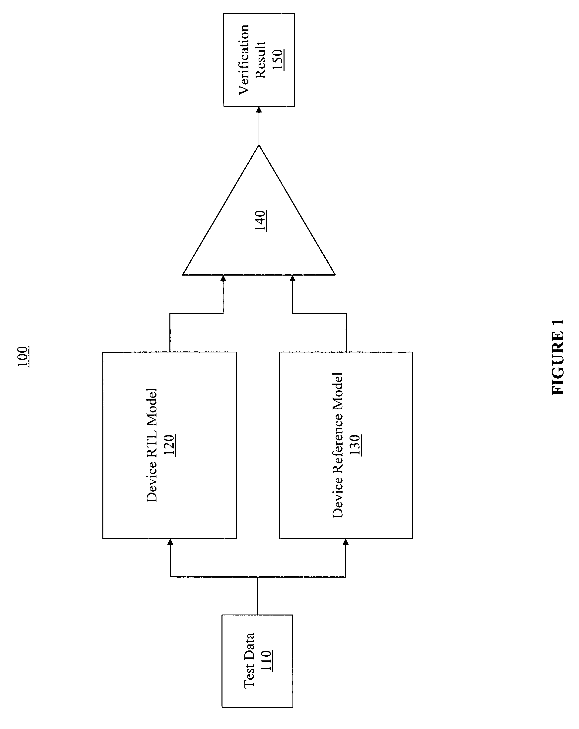
BACKGROUND OF THE INVENTION[0001]Verification of a design is commonly used in the production of integrated circuits for bug-finding and debugging prior to manufacturing the design. Verification is typically performed by applying a test file to a device RTL model and a device reference model, where the output from each may be compared and analyzed. The test file is created by the design or verification engineer in an attempt to exercise various portions of the RTL model code during the verification process. Exercising of the code may be used to complete code coverage goals and / or functional coverage goals.[0002]Prior to comparing the output from the RTL model and the reference model, the test file is created to accomplish code coverage goals and / or functional coverage goals. The functional coverage goals must be specified by the design or verification engineer. Conventional methods of creating test files involve the design or verification engineer writing an initial test file and sim...

Claims


Application Information

Patent Timeline
Patent Type & Authority Patents(United States)
IPC IPC(8): G06F17/50
CPCG06F11/261G06F17/5022G06F30/33
Inventor CHATTERJEE, PROSENJITNG
Owner NVIDIA CORP
Learn More