
Light emitting devices with phosphosilicate glass

a light-emitting device and phosphosilicate glass technology, applied in the direction of lasers, instruments, active medium materials, etc., can solve the problems of pulse deformation, limit the amount of energy that may be extracted, create non-linear effects, etc., and achieve the effect of reducing the photodarkening

Active Publication Date: 2012-09-18
CORACTIVE HIGH TECH
View PDF30 Cites 28 Cited by
  • Summary
  • Abstract
  • Description
  • Claims
  • Application Information

AI Technical Summary

Benefits of technology

[0015]The at least one active ion dopant may induce a photodarkening effect in optical properties of the optically-active glass and the phosphorous oxide may be present in an effective amount for reducing the photodarkening effect.

Problems solved by technology

The main limitations for achieving high peak powers inside optical fibers are due to small mode size and large propagation length, which can create non-linear effects.
Another problem with some gain media having high-emission cross sections is that the saturation energy per unit area is low, which consequently limits the amount of energy that may be extracted and causes pulse deformation.
Longitudinal mode beating can be an important source of high frequency noise which consequently gives rise to peak power fluctuations in the pulse structure of a pulsed amplifier or laser.
Depending on its amplitude and frequency spectrum, this noise can severely limit the ability to generate stable optical pulses having special shapes with fine structures.
Another problem encountered with high-energy amplifiers and lasers are the non-linear effects that appear at high energies.
The onset of non-linear effects can severely degrade the spectral content and limit the power output of the laser source.
For some rare-earth doped core compositions, photodarkening (i.e. the formation of photoinduced structural transformations) over time induces losses in the doped glass core of the fibers resulting in reduced output power efficiency of the fibers.

Method used


Image

  • Light emitting devices with phosphosilicate glass
  • Light emitting devices with phosphosilicate glass
  • Light emitting devices with phosphosilicate glass

Examples


Embodiment Construction

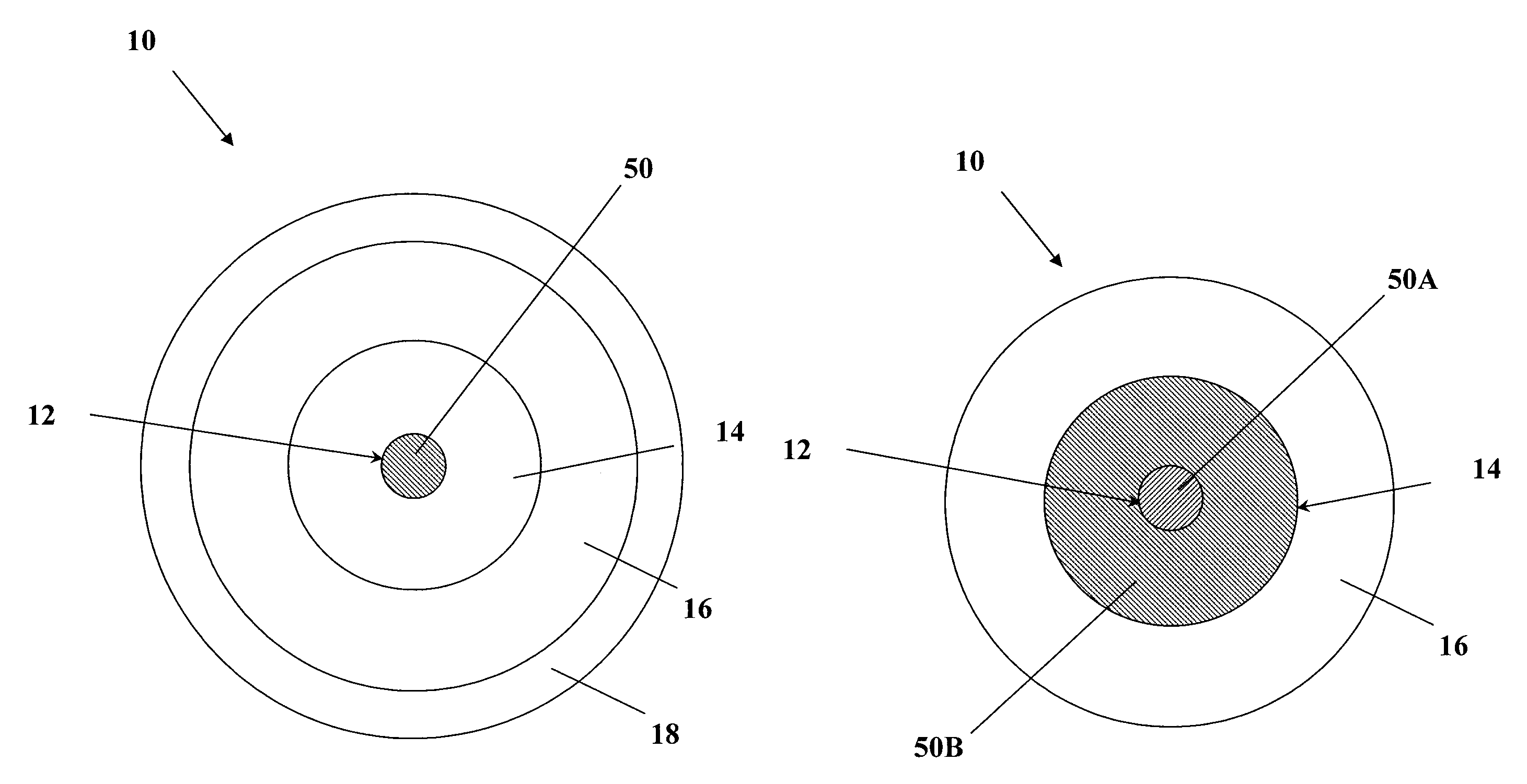
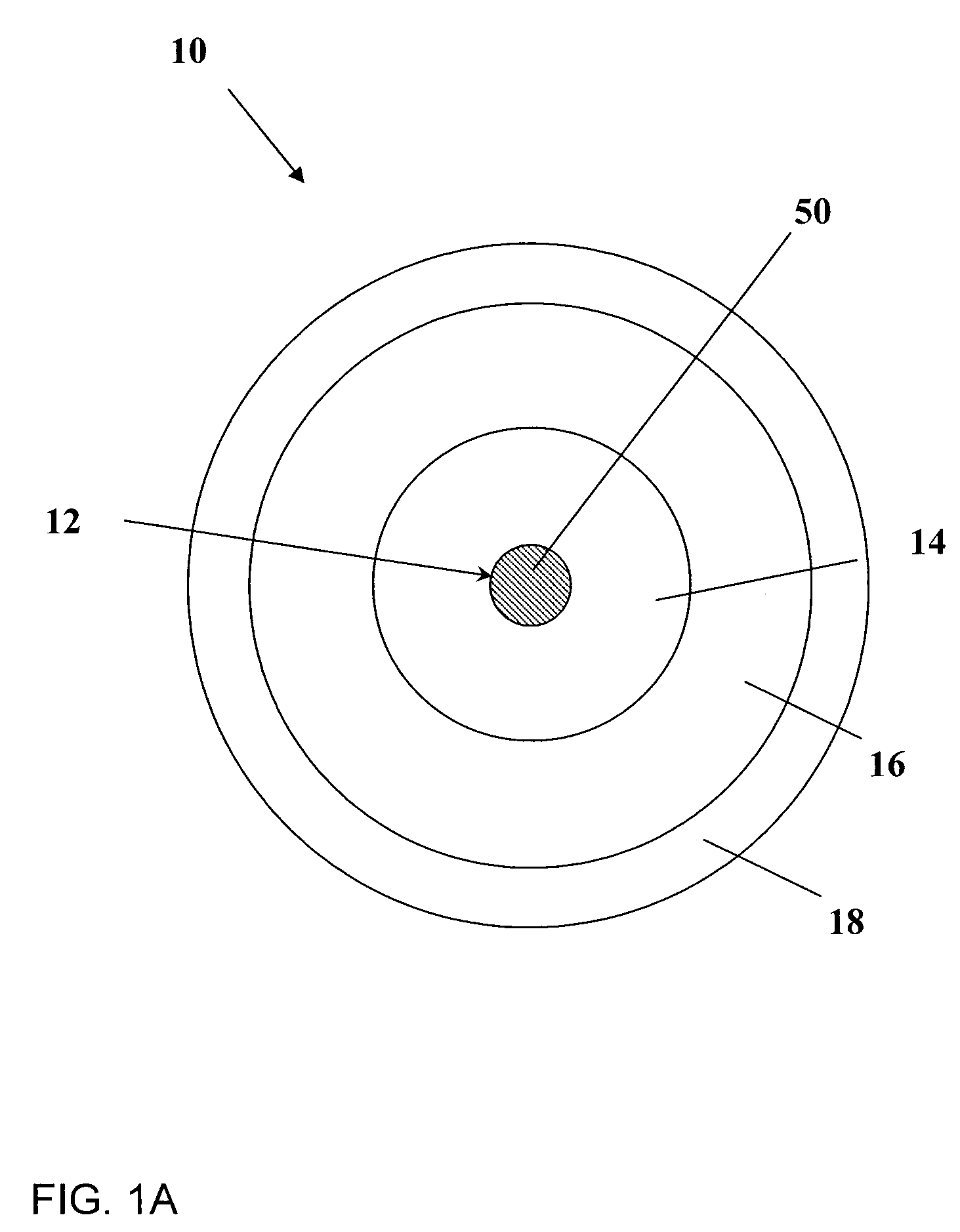
[0042]The present invention will be described more fully hereinafter with reference to the accompanying drawings, FIGS. 1A to 9C, in which like numerals refer to like elements throughout.

[0043]In the following description, the term “light” is used to refer to all electromagnetic radiation, including but not limited to visible light. Furthermore, the term “optical” is used to qualify all electromagnetic radiation, that is to say light in the visible spectrum and light in other wavelength (λ) ranges.

[0044]According to one aspect, the invention provides a light-emitting device which includes a gain medium that includes an optically active phosphosilicate glass, the phosphosilicate glass having at least one active ion dopant and from about 1 to 30 mol % of phosphorus oxide.

[0045]The light-emitting device may emit light and alternatively or additionally it may amplify light. Although the light-emitting device is preferably embodied by an amplifier or a pulsed amplifier, it may be embodie...


PUM


Abstract

A light-emitting device is provided which includes a gain medium having an optically-active phosphosilicate glass, wherein the phosphosilicate glass includes at least one active ion dopant and from about 1 to 30 mol % of phosphorus oxide. The phosphorous oxide may be present in an effective amount for reducing any photodarkening effect and increasing the saturation energy of the system. The active ion dopant may be a rare earth dopant. The light-emitting device may include an optical waveguide, the optical waveguide including the gain medium. The optical waveguide may have a core and at least one cladding, and the gain medium having the phosphosilicate glass may be found in the core and / or in one of the cladding.

Description

CROSS-REFERENCE TO RELATED APPLICATION[0001]This application is a National Stage Application of PCT / CA2008 / 001296, filed 15 Jul. 2008, which claims benefit of U.S. Ser. No. 60 / 929,864, filed 16 Jul. 2007 and which applications are incorporated herein by reference. To the extent appropriate, a claim of priority is made to each of the above disclosed applications.[0002]This application contains subject matter which is related to the subject matter of commonly assigned US, Patent Application Publication No. US 2009-0011233 A1, publication date Jan. 8, 2009, which is incorporated herein by reference in its entiretyFIELD OF THE INVENTION[0003]The present invention relates generally to optically active glass and light emitting devices including such glass. More specifically, the invention relates to phosphosilicate optical waveguides and high output power amplifiers or lasers including the same.BACKGROUND OF THE INVENTION[0004]Optical fiber lasers and amplifiers used in the amplification ...

Claims


Application Information

Patent Timeline
Patent Type & Authority Patents(United States)
IPC IPC(8): H01S3/17
CPCG02B6/03616H01S3/175H01S3/06716H01S3/1618G02B6/03633G02B6/03638H01S3/06729H01S3/06745H01S3/06754H01S3/176H01S3/06733H01S3/0675
Inventor MORASSE, BERTRANDDE SANDRO, JEAN-PHILIPPEGAGNON, ERICCHATIGNY, STEPHANE
Owner CORACTIVE HIGH TECH
Learn More