Metal stencil coin repair method

Inactive Publication Date: 2012-09-04
YOUR DENT GUY
View PDF30 Cites 2 Cited by
  • Summary
  • Abstract
  • Description
  • Claims
  • Application Information

AI Technical Summary

Benefits of technology

[0011](1) New tool tips for repairing coins. The tips first used in repair attempts were formed of metal and too sharply tipped. This would tend to scar the surface of the repair. Custom tips were developed made out of soft plastic or rubber and having various tip shapes, from sharp to very blunt, for different types of coins. These new tips give a technician much more control of how much surface area of the stencil is manipulated at one time, in order to avoid the scarring the stencil further.
[0012](2) New hand tool for carrying tool tips. Many of the tools of the auto paintless dent repair business are very long, in order to provide the technician the necessary leverage to repair coins in the sheet metal. These tools provide far more leverage than is appropriate for stencil coins and are also difficult to manipulate with the delicacy and control needed for stencil coins. Repairing a damaged stencil takes a very steady hand. Applicant developed a new handle—a modification of a blank screwdriver handle. The new handle facilitates direct application (rather than a leveraged application) of pressure. It also facilitates far lighter and more delicate control of pressure.
[0014](4) Orientation of a straight-line light source to illuminate defects. Previously, applicant had attempted to illuminate the surface of the metal stencil with washed white lighting. The washed lighting, however, failed to reveal many defects that potentially interfered with the squeegee solder application. It also failed to provide adequate visual feedback when attempting to repair a coin. Repairing a damaged stencil requires not only a very steady hand, but also very good visual feedback and hand-eye coordination. After experimentation, applicant began using an adjustable stand-mounted straight-line light source to identify defects. Distortions in the reflected light pattern proved useful in both identifying defects, locating the proper place to apply tool tip pressure, and calibrating the amount of pressure to apply. For some stencil repairs, lines of different color tapes were applied to the light fixture and bulb to give a “straight edge” in the reflection. The lines on the light improved the ability to see more exact detail as the repair proceeded.
[0023]There is a long-felt need and significant advantages to the invention. Repairing coining damage on metal stencils saves time, expense and materials for manufacturers when any stencils are damaged because they will be able to do in house repairs instead of ordering a replacement stencil. With the inventive process repairs can be done on site in less than an hour using the existing damaged stencil in its frame mounting.

Problems solved by technology

The applicant's repair attempts at that time, using the normal tools and techniques of the paintless dent repair trade, failed.
Because the metal stencils were extremely thin, attempts to repair a coin frequently resulted in greater damage.
Moreover, applicant was unable to repair coins to satisfaction, that is, within the tolerance ranges required for solder application.
Because applicant's efforts proved unsuccessful, the applicant temporarily discontinued those efforts.
(1) New tool tips for repairing coins. The tips first used in repair attempts were formed of metal and too sharply tipped. This would tend to scar the surface of the repair. Custom tips were developed made out of soft plastic or rubber and having various tip shapes, from sharp to very blunt, for different types of coins. These new tips give a technician much more control of how much surface area of the stencil is manipulated at one time, in order to avoid the scarring the stencil further.

Method used


Image

  • Metal stencil coin repair method
  • Metal stencil coin repair method
  • Metal stencil coin repair method

Examples


Embodiment Construction

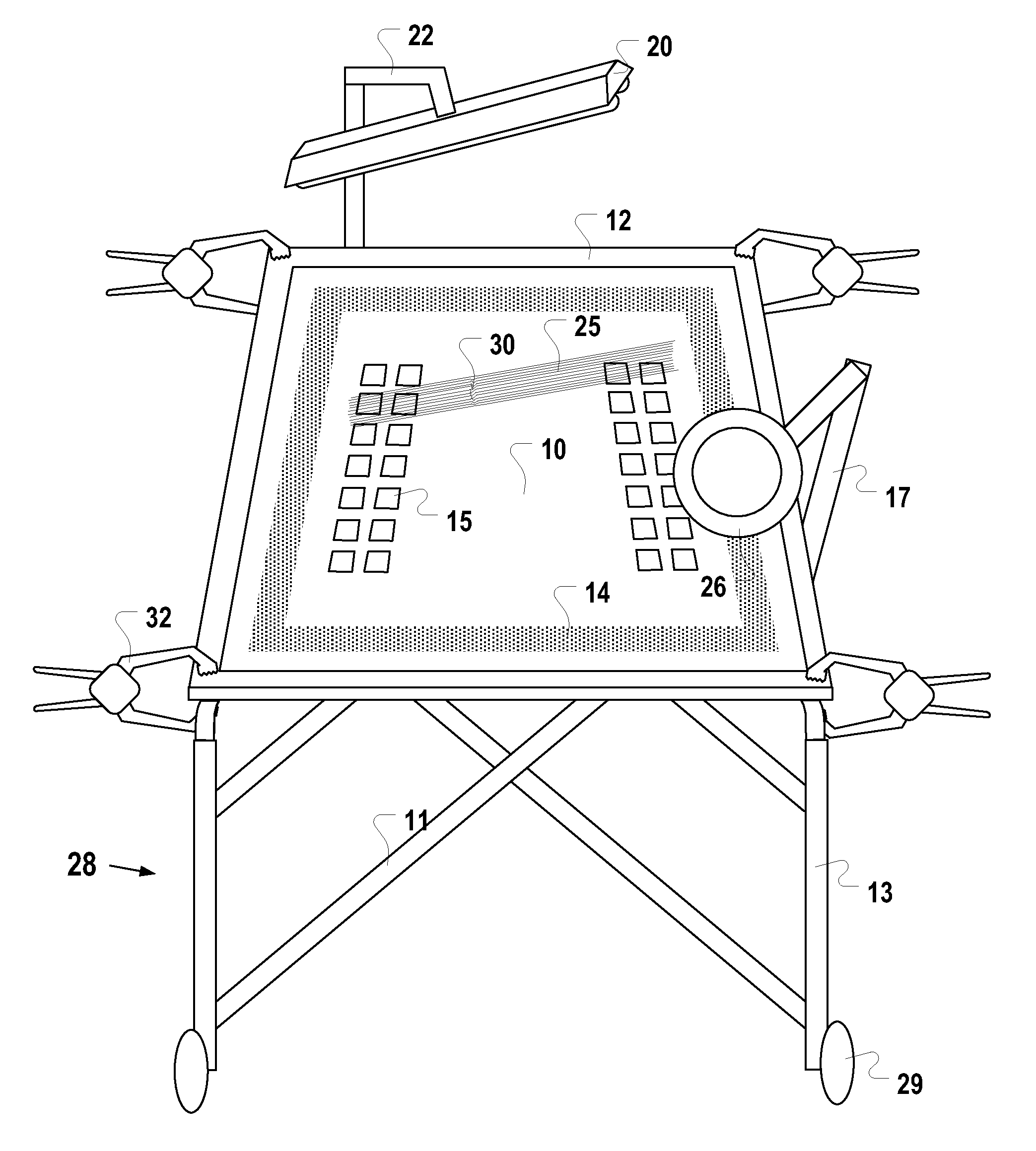
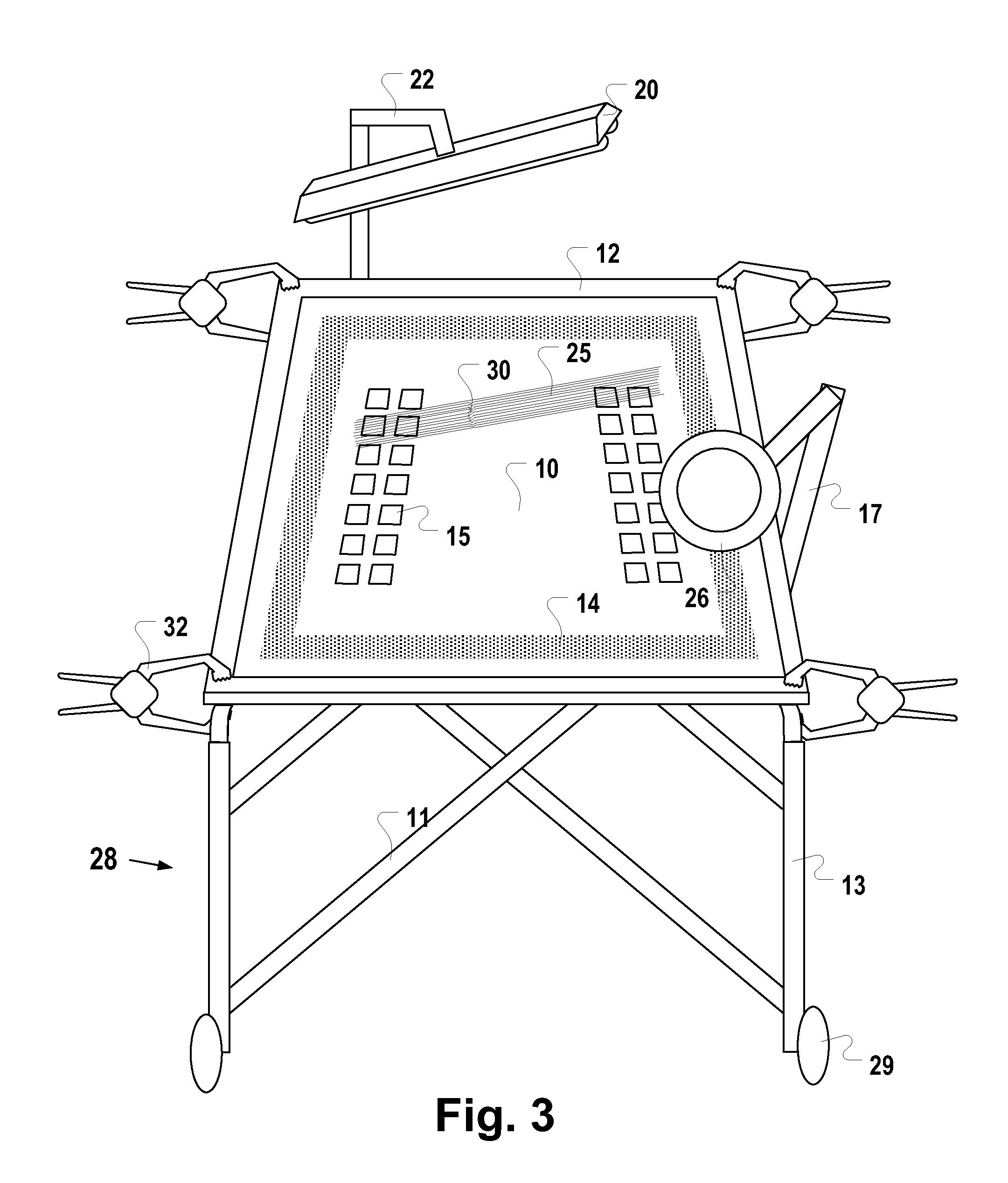
[0049]FIG. 1 illustrates one embodiment of a framed metal stencil 10. The metal stencil 10 is held in tension, at about 40-50 pounds of pressure, by metal stencil frame 12. The metal stencil 10 is glued to, and held taut, by screen 14. In some embodiments, the metal stencil 10 is made of stainless steel. In yet others, it is made of a brass alloy. Generally, the metal stencil 10 is moderately reflective, providing a moderately mirror-like reflection.

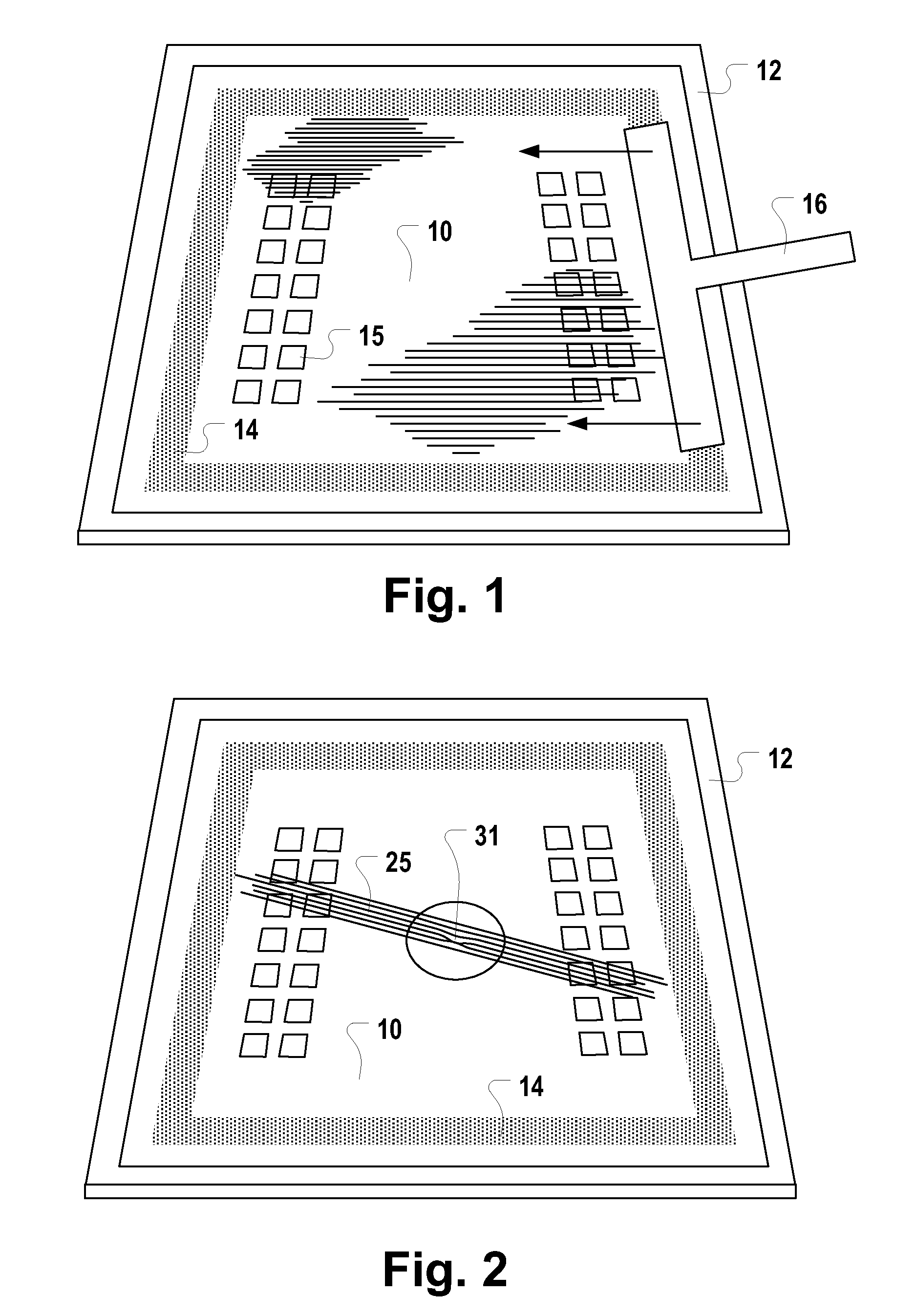
[0050]In operation, the metal stencil 10 is precisely positioned, as a mask, over a plurality of printed circuit boards. FIG. 1 illustrates a series of rectangles 15. Each rectangle 15 is positioned over a corresponding circuit board. Each rectangle 15 comprises hundreds of small circular holes or apertures (not shown because of their small relative size) through which solder is squeezed onto the conducting pads of the circuit board. FIG. 1 also illustrates the direction of travel of a squeegee 16 used to apply the solder.

[0051]Even smal...


PUM

PropertyMeasurementUnit
Pressureaaaaaaaaaa
Diameteraaaaaaaaaa
Widthaaaaaaaaaa

Abstract

During the manufacture of printed circuit boards, metal stencils are used as a mask over which a blade is used to squeegee solder through stencil holes onto conducting pads of the circuit board. A typical stencil is both expensive and delicate. Even minor dents, creases, or impressions (commonly referred to as “coins”) in the stencil can result in circuit board defects. Manufacturers frequently suffer significant losses scrapping their coined stencils and idling manufacturing lines while waiting for replacement stencils to be fabricated, shipped, and installed. An apparatus and method is provided for repairing metal stencil coins.

Description

RELATED APPLICATIONS[0001]This application claims priority to and incorporates by reference my U.S. provisional application No. 61 / 147,120, filed Jan. 25, 2009, entitled “Metal Stencil Coin Repair Method.”FIELD OF THE INVENTION[0002]The invention relates generally to paintless dent repair, and more particularly to several modifications of the tools and techniques of the trade to repair surface defects such as dents, creases, and impressions on solder stencils, especially framed metal stencils, used for solder paste printing of circuit boards.BACKGROUND OF THE INVENTION[0003]During the manufacture of printed circuit boards, metal foil stencils are used to deposit solder. The metal stencil serves as a mask over which a blade is used to squeegee solder through stencil holes onto conducting pads of the circuit board. A variety of background information about stencils can be found in U.S. Pat. Nos. 4,486,466; 4,893,403; 4,789,096; 4,976,813; 5,359,928; 5,493,075; 5,746,127; 5,800,856; 5,...

Claims


Application Information

Patent Timeline
IPC IPC(8): B23P6/00B21D31/00
CPCH05K3/1225H05K13/06Y10T29/49748Y10T29/49718
Inventor BISHOP, JAMES M.
Owner YOUR DENT GUY
Why Eureka
Try Eureka