
Repair technique for lightning strike protection

a technology of composite aircraft skin panels and repair techniques, which is applied in the direction of aircraft static dischargers, emergency protective arrangements for limiting excess voltage/current, etc., can solve the problems of increasing the potential difference produced across the ply structure, arcing, sparks and other unwanted effects, and no readily available electrically conductive path for discharging current, etc., to achieve the effect of reducing the chance of arcing or sparks, reducing the density of current through fasteners, and reducing the chance o

Active Publication Date: 2012-07-31
THE BOEING CO
View PDF23 Cites 3 Cited by
  • Summary
  • Abstract
  • Description
  • Claims
  • Application Information

AI Technical Summary

Benefits of technology

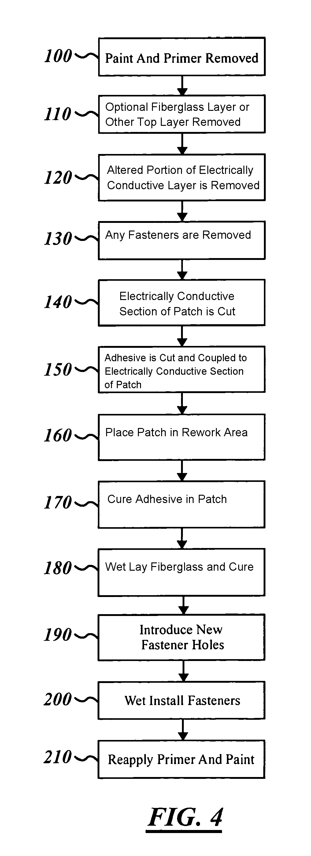
The present patent provides a method for reestablishing the electrical continuity of an electrically conductive layer on an aircraft wing that has been altered by a lightning strike or other means. The method involves replacing the altered section of the electrically conductive layer with a copper patch and a specialized adhesive layer, which has a low dielectric breakdown strength. This adhesive layer allows electricity to pass through it, reducing current density through fasteners and minimizing the chances of arcing or sparks. The use of an unsupported film adhesive is preferred to increase the effectiveness of protection against lightning strikes. The method can be used to rework a composite skin layer that has been altered by a lightning strike or other means.

Problems solved by technology

In a carbon fiber composite structure, which is approximately 2000 times more resistive than aluminum, the carbon fiber plies act as very high resistance conductors and the resin between the plies acts as highly capacitive dielectric layers so that lightning striking the carbon fiber composite results in an increasing potential difference produced across the ply structure but no readily available electrically conductive path for discharging the current.
When the lightning energy is unable to dissipate at a fast enough rate, arcing, sparks and other unwanted effects may occur.
In addition, it is difficult to achieve a satisfactory electrical bond using either of these processes.
The protective conductive layer also adds mass without contributing to the strength of the assembled structure, is vulnerable to environmental damage, and is difficult to maintain.
The production and maintenance of such an arrangement is thus clearly expensive.
However, the use of woven screens or foils requires the use of an additional ply of fiberglass when the non-metallic structure is carbon to electrically isolate the carbon layer from the metal to prevent corrosion and that also adds non-structural weight.
Again, this approach to the problem of arcing is expensive because of the need for special fastener designs.
While the Pridham disclosure effectively protects the fuel system from lightning strikes, the proposed system does not address the need for repairing the electrically conductive layer after a lightning strike or after other alteration.
This may reduce the effectiveness of the protection against lightning strikes, as there would be a higher current density through fasteners.

Method used


Image

  • Repair technique for lightning strike protection
  • Repair technique for lightning strike protection
  • Repair technique for lightning strike protection

Examples


Embodiment Construction

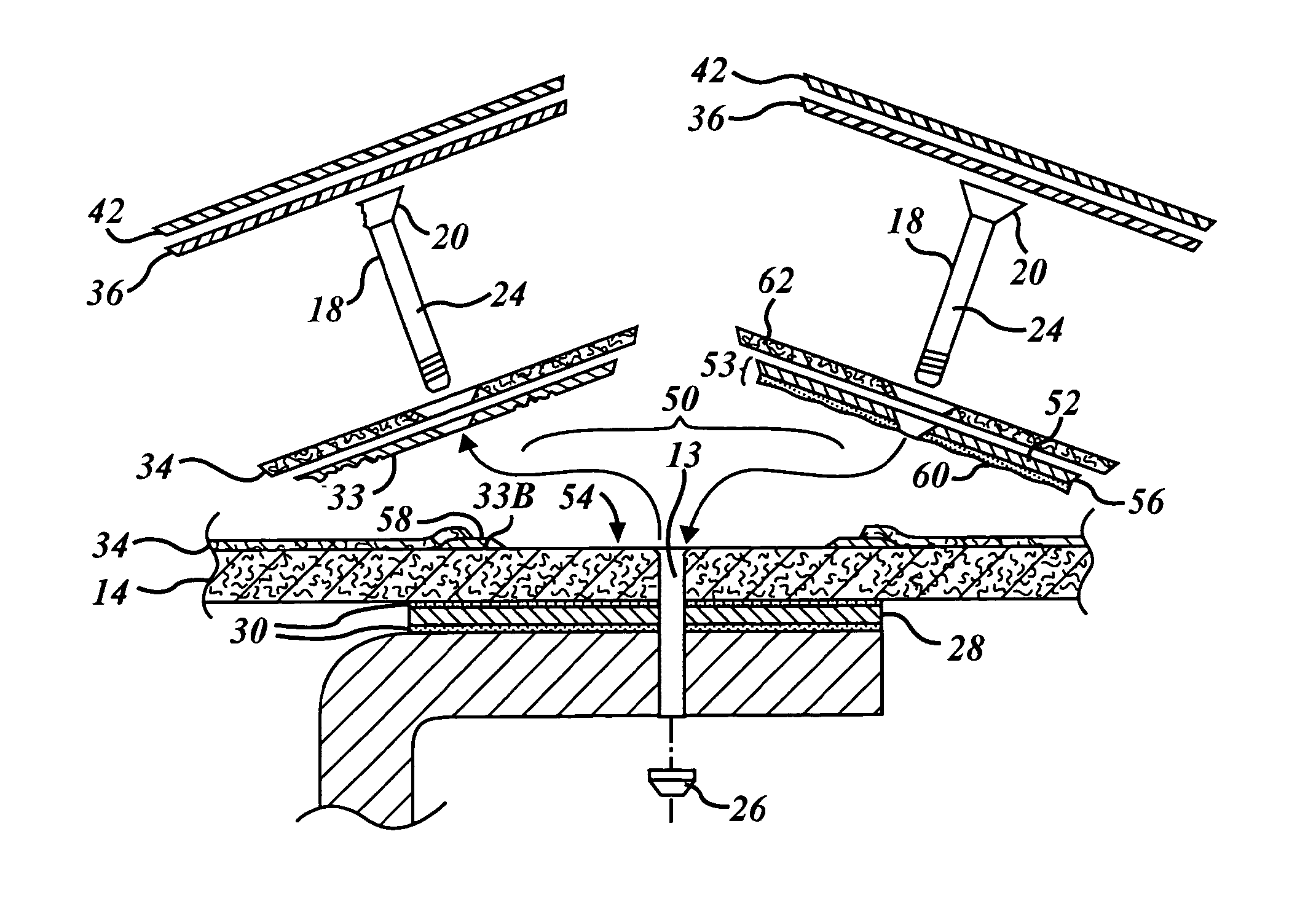
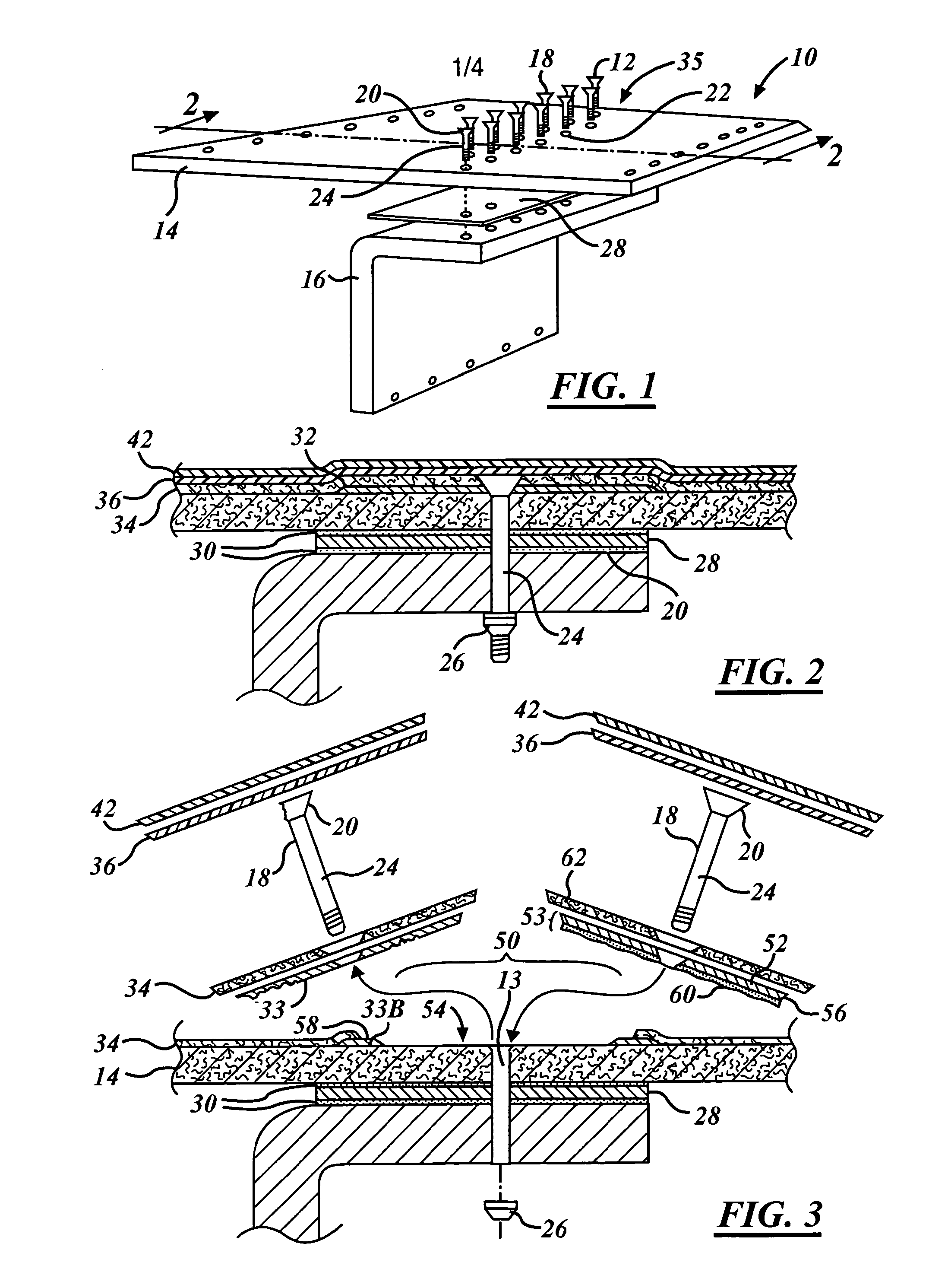
[0021]The methods for reworking an altered aircraft composite structure having an electrically conductive layer will now be described in the context of a composite aircraft wing 10, whose structure will be described below, with respect to FIGS. 1 and 2. However, nothing in this disclosure should be construed to limit this method to an aircraft wing 10. It should be understood that the method can be applied to other structures, as one of ordinary skill in the art would recognize.

[0022]Referring now to FIGS. 1 and 2, a section and perspective view of a portion of a wing structure 10 of an aircraft showing a plurality of fasteners 12 is shown securing a skin panel 14 of an aircraft structure to an inner substructure or spar 16, comprising the wall of a fuel tank (not shown).

[0023]The skin panel 14 and the spar 16 are made of carbon fiber composite material of low weight and high strength and stiffness formed by conventional methods well known in the art. For example, in one preferred f...


PUM

PropertyMeasurementUnit
temperatureaaaaaaaaaa
thicknessaaaaaaaaaa

Abstract

A method for reworking an electrically conductive layer of a composite skin is disclosed in which a patch replaces the altered section of the electrically conductive layer. The method is performed by removing a portion of the electrically conductive layer to reveal the underlying composite skin. A patch is formed, having an electrically conductive section coupled to an adhesive having a low dielectric breakdown strength, and is then introduced over the underlying composite skin such that the adhesive layer covers the underlying composite skin and overlaps an unremoved portion of the electrically conductive layer. The patch is applied such that the electrically conductive section within the patch covers the adhesive layer and overlaps the unremoved section of the electrically conductive layer. The adhesive layer preferably has a low dielectric breakdown strength, so that electricity from lightning which strikes the composite skin may be conducted through the adhesive.

Description

RELATED APPLICATIONS[0001]This application is a continuation-in-part of application Ser. No. 11 / 220,046 filed Sep. 6, 2005, now U.S. Pat. No. 7,686,905, the disclosure of which is incorporated herein by reference.TECHNICAL FIELD[0002]This application generally relates to aircraft lightning strike protection techniques and, more specifically, to a copper grid repair technique for composite aircraft skin panels.BACKGROUND ART[0003]The use of carbon fiber reinforced plastic (“CFRP”) materials, otherwise known as carbon fiber composites, for structural members is increasing in commercial airplanes because of the higher strength-to-weight and stiffness-to-weight ratios afforded by carbon fiber composites as compared to traditional aluminum structures.[0004]A lightning strike to an aircraft causes a high electric current, which may typically be of the order of 100,000 amps, to flow through the aircraft frame. In a carbon fiber composite structure, which is approximately 2000 times more re...

Claims


Application Information

Patent Timeline
Patent Type & Authority Patents(United States)
IPC IPC(8): B29C73/00B64D7/00B29C65/00H02H3/22H05F3/00H02H9/06B32B37/00B32B43/00B64C1/10H02H1/00H02H1/04B64D45/02
CPCB29C73/10B64F5/0081B64D45/02B29L2031/3085Y10T428/20Y10T156/109B64F5/40
Inventor ACKERMAN, PATRICEBLANCHARD, STEVENKOVACH, DANIEL
Owner THE BOEING CO
Learn More