Vapor grown carbon fiber, production method thereof and composite material containing the carbon fiber

a technology of carbon fiber and composite materials, which is applied in the direction of carbonsing rags, transportation and packaging, physical/chemical process catalysts, etc., can solve the problems of unsatisfactory electrical conductivity of composite materials containing carbon fibers, and achieve excellent electrical conductivity and thermal conductivity

Active Publication Date: 2012-06-26
RESONAC HOLDINGS CORPORATION
View PDF36 Cites 2 Cited by
  • Summary
  • Abstract
  • Description
  • Claims
  • Application Information

AI Technical Summary

Benefits of technology

[0006]An object of the present invention is to provide a carbon fiber which, when added to a matrix such as a resin in a smaller amount as compared with the case of conventional vapor grown carbon fiber, can impart excellent electrical conductivity and thermal conductivity thereto. Another object is to provide a method for producing the carbon fiber.
[0007]The present inventors have reviewed reaction conditions for producing vapor grown carbon fiber through thermal decomposition of a carbon source, and have found that when a uniformly mixed gas containing a carbon source and a transition metal compound serving as a catalyst is sprayed toward the inner wall of a reactor, carbon fiber having a specific fiber diameter and a specific aspect ratio is produced, and that when the thus-produced carbon fiber is added to a matrix such as a resin to prepare a composite material, even if the addition amount of the carbon fiber is considerably small as compared with the case of conventional vapor grown carbon fiber, the composite material exhibits excellent electrical conductivity and thermal conductivity. The present invention has been accomplished on the basis of these findings.

Problems solved by technology

However, with the small fiber diameter 3.5 to 70 nm of this carbon fiber, the specific surface area is large and the surface energy is high and therefore, the carbon fiber involves problems in that the carbon fiber tends to form an aggregate, that the carbon fiber is difficult to disperse in a resin, and that therefore, a composite material containing the carbon fiber exhibits unsatisfactory characteristics such as electrical conductivity.

Method used


Image

  • Vapor grown carbon fiber, production method thereof and composite material containing the carbon fiber
  • Vapor grown carbon fiber, production method thereof and composite material containing the carbon fiber
  • Vapor grown carbon fiber, production method thereof and composite material containing the carbon fiber

Examples


example 1

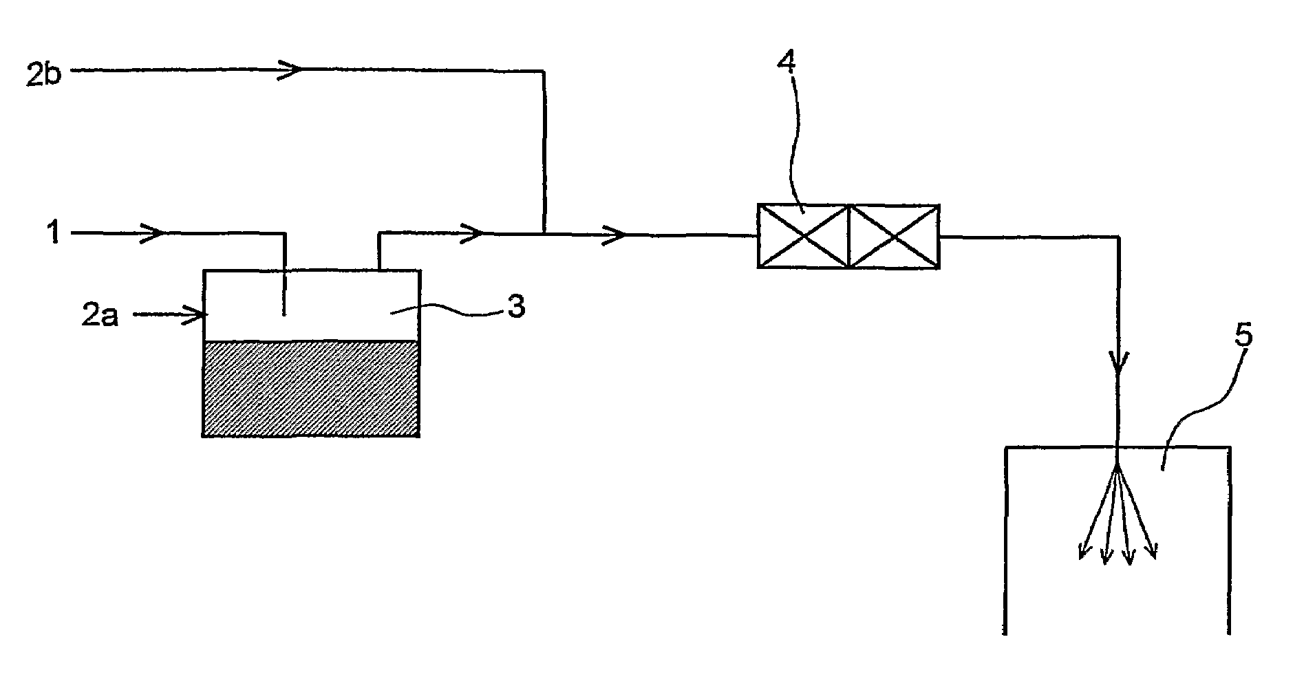
[0046]Vapor grown carbon fiber was produced by use of apparatuses as shown in the flow diagram of FIG. 1.

[0047]As a reaction tube (5) was employed a vertical heating furnace (inner diameter: 370 mm, length: 2,000 mm) having, on its top, a nozzle unit for supplying raw material gas.

[0048]The temperature of a gasifier (3) was regulated to 500° C. Nitrogen gas was caused to pass through the reaction system, to thereby purge oxygen gas from the system. Subsequently, hydrogen gas was caused to pass through the system, to thereby fill the system with hydrogen gas. Thereafter, the temperature of the reaction tube was elevated to 1,250° C. Reaction was initiated by feeding a liquid raw material (30 g / min) into the gasifier by use of a pump. The thus-gasified raw material was fed into a path by use of hydrogen gas (50 L / min) serving as a carrier gas. Before being fed into the reaction tube, the raw material gas was further mixed with hydrogen gas (400 L / min) by use of a static mixer (4). The...

example 2

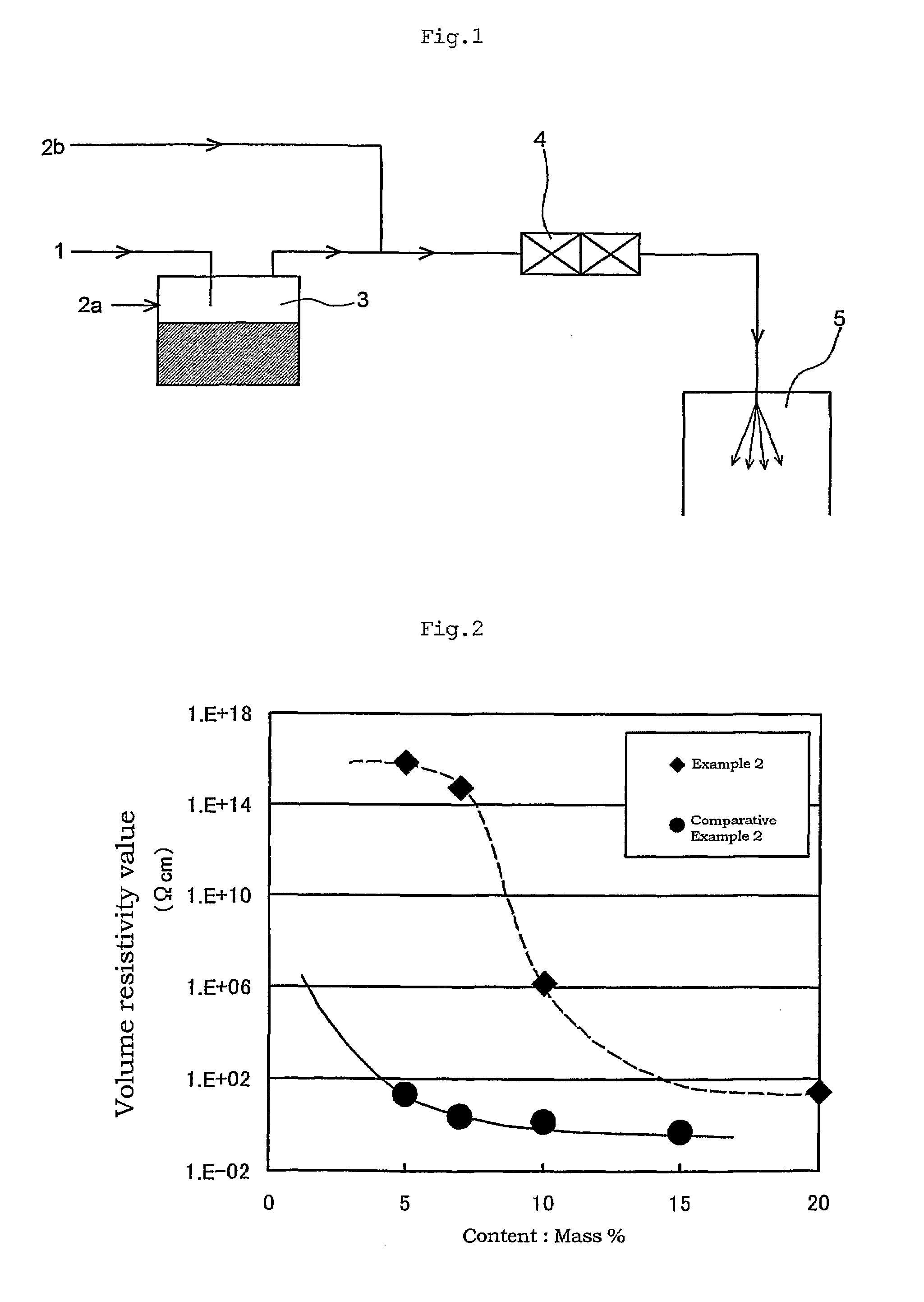
[0053]By use of a 30-mmφ one-directional twin-screw extruder (product of Ikegai, Ltd.), the vapor grown carbon fiber produced in Example 1 was dispersed in polycarbonate in different amounts ranging from 5 to 15 mass %, to thereby prepare different carbon fiber / polycarbonate composite materials. The preparation rate was regulated to 3 kg / h. Each of the thus-prepared composite materials was molded into a plate (100 mm×100 mm×2 mm thick) by use of a 75-t injection molding apparatus (product of FANUC LTD.). The volume resistivity of the plate was measured by means of the four-probe method. The results are shown in FIG. 2.

example 3

[0054]The vapor grown carbon fiber produced in Example 1 was compressed to a density of 0.1 g / cm3, and then the thus-compressed fiber was milled by use of a feather mill, to thereby yield carbon fiber having a bulk density of 0.04 g / cm3. By use of a 30-mmφ one-directional twin-screw extruder (product of Ikegai, Ltd.), the resultant carbon fiber was dispersed in polycarbonate in an amount of 5 mass %, to thereby prepare a carbon fiber / polycarbonate composite material. The preparation rate was regulated to 10 kg / h. The thus-prepared composite material was molded into a plate (100 mm×100 mm×2 mm thick) by use of a 75-t injection molding apparatus (product of FANUC). The volume resistivity of the plate was measured by means of the four-probe method, and was found to be 1×10² Ωcm.


PUM

PropertyMeasurementUnit
densityaaaaaaaaaa
diameteraaaaaaaaaa
aspect ratioaaaaaaaaaa

Abstract

The invention relates to a vapor grown carbon fiber having a mean fiber diameter of 80 to 500 nm, an aspect ratio of 100 to 200 and preferably a bulk density of 0.02 g / cm3 or less, wherein filaments having a diameter within ±20% of the mean fiber diameter occupies 65% (on a number basis) or more of the total. The production method involves thermal decomposition of a carbon source at 800 to 1,300° C. in the presence of, as a catalyst, a transition metal compound having a vapor pressure of 0.13 kPa (1 mmHg) or more at 150° C. and spraying of the carbon source and the transition metal compound in gas form toward the reactor inner wall to allow reaction to proceed. The vapor grown carbon fiber having a larger aspect ratio has excellent dispersibility, and when added in a resin, a smaller amount contributes to enhancement in electroconductivity and thermal conductivity, as compared with a case using conventional one.

Description

CROSS-REFERENCE TO RELATED APPLICATIONS[0001]This is an application filed pursuant to 35 U.S.C. Section 111(a) with claiming the benefit of U.S. provisional application Ser. No. 60 / 578,850 filed Jun. 14, 2004 and U.S. provisional application Ser. No. 60 / 607,597 filed Sep. 8, 2004 under the provision of 35 U.S.C. 111(b), pursuant to 35 U.S.C. Section 119(e)(1).TECHNICAL FIELD[0002]The present invention relates to a vapor grown carbon fiber. More particularly, the present invention relates to a vapor grown carbon fiber which, when dispersed in a matrix such as a resin for preparation of a composite material, exhibits a performance comparable to that of the conventional vapor grown carbon fiber, even in a use amount half or less than the use amount of conventional vapor grown carbon fiber, to a method for producing the carbon fiber; and to a composite material containing the carbon fiber.BACKGROUND ART[0003]Dispersing carbon fiber in a matrix such as a resin is a widely and commonly pe...

Claims


Application Information

Patent Timeline
Patent Type & Authority Patents(United States)
IPC IPC(8): C01B31/00B82B1/00B82B3/00C01B31/02C01B31/08C01B31/10D01F9/12D01F9/127C01B32/336C04B35/80D06M11/01D06M11/34
CPCB82Y30/00C08J5/042C08K7/06D01F9/127D01F11/10D06M11/34C08K3/04Y10S977/754Y10T428/2918Y10T428/298Y10S977/84Y10S977/833Y10S977/832C08K2201/016
Inventor YANO, KOTAROYAMAMOTO, RYUJIMORITA, TOSHIO
Owner RESONAC HOLDINGS CORPORATION
Why Eureka
Try Eureka