
Spacer fabric

a spacer fabric and fabric technology, applied in the field of spacer fabrics, can solve the problems of undesirable energy and heat loss in the lead and at the contact point, non-negligibility, and high cost of materials, and achieve the effect of good electrical conductivity of the spacer fabri

Active Publication Date: 2022-02-08
MULLER TEXTIL
View PDF21 Cites 1 Cited by
  • Summary
  • Abstract
  • Description
  • Claims
  • Application Information

AI Technical Summary

Benefits of technology

[0016]Since the two knitted layers and the spacer yarns are composed at least partially of metal braids, the overall result is a very high metal content of usually at least 70% by weight and preferably at least 80% by weight. The weight per unit area is typically between 0.25 kg / m2 (kilograms per square meter) and 2.5 kg / m2. In particular, the weight per unit area can be between 1 kg / m2 and 2 kg / m2, for example about 1.8 kg / m2. The high metal content of up to 100% and the high weight per unit area also result in comparatively high production costs.
[0018]According to an especially preferred embodiment of the invention, the metal braid is formed by appropriately individual tinned copper wires. Copper is characterized by very good thermal and electrical conductivity and is inexpensive compared to more noble metals such as silver and gold. If the strands of the metal braid are also tin plated, good protection also exists against corrosion. Moreover, as will be described in detail below, the metal braid can then also be soldered in a particularly simple manner.
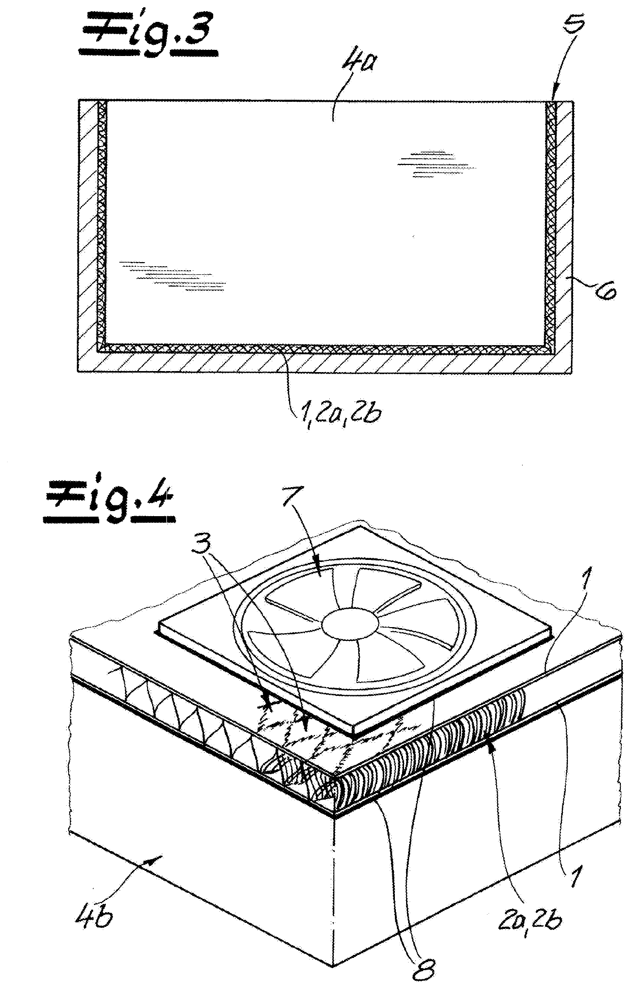
[0029]According to a preferred development of such a use, if the knitted spacer fabric is connected to an electrical component for heat dissipation, the knitted spacer fabric can be fitted in a thermally conductive manner, for example, tightly in a gap between a housing and the electrical component, thus bridging the gap. The knitted spacer fabric can then be used in this way to compensate for manufacturing tolerances and to allow for optimal cooling of the electrical component via the surrounding housing.
[0030]According to an alternative development of the use according to the invention, the knitted spacer fabric is connected as a heat sink to an electronic component as an electrical component. Conventional heatsinks for electronic components are usually embodied as milled or injection-molded parts, with the largest possible surface being provided by cooling fins. With the knitted spacer fabric according to the invention, when used as a heat sink, a particularly large surface area can be achieved with a comparatively low weight, with the flowability with a fluid flow, particularly air flow, also being improved. When used as a heat sink of an electrical component, the knitted spacer fabric according to the invention can contribute to a reduction in both weight and cost.
[0031]Especially good cooling, that is, heat exchange with the environment, can be achieved when air is pumped through the knitted spacer fabric. The knitted spacer fabric can thus be blown on by a fan or appropriately positioned in an air flow. In addition, it is also possible to connect a fan to the knitted spacer fabric that is then even shock-damped to some extent by the elastically resilient properties of the knitted spacer fabric. Particularly under harsh operating conditions, the lifetime of such a fan can thus be substantially extended.
[0033]In addition to the preferred use as a heat conduction layer that is connected to an electrical component for heat dissipation, other applications are also possible. For example, the good electrical conductivity of the knitted spacer fabric can also be exploited, in which case, unlike with resistance heating, there should actually be no losses at the knitted spacer fabric itself. The knitted spacer fabric can be provided, for example, as an elastic and flexible electrical contact layer. In addition, it may also be desirable to use the knitted spacer fabric for grounding and / or shielding.

Problems solved by technology

In order to achieve the desired heating effect for resistance heating, the specific resistance is too low precisely in a configuration with a knitted layer that is composed entirely of metal braid, resulting in non-negligible, undesirable energy and heat losses in the leads and at the contact points.
Moreover, due to its high metal content, the material is very expensive and not economically competitive compared to other spacer fabrics for seat heaters that were also mentioned above that contain only a proportion of metallic yarns and / or coated plastic yarns.

Method used


Image

  • Spacer fabric
  • Spacer fabric

Examples


Embodiment Construction

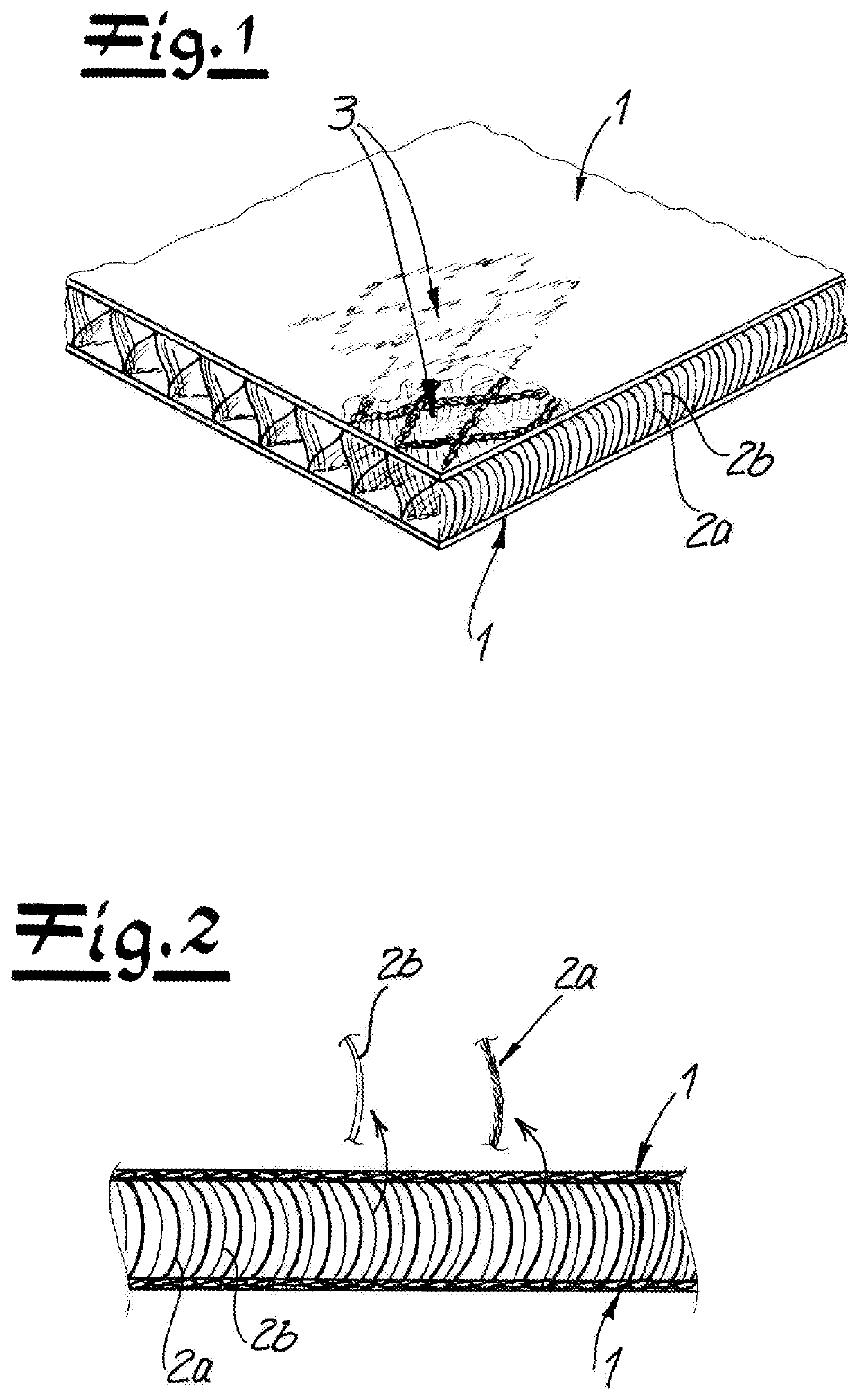
[0039]As seen in FIG. 1, a knitted spacer fabric has two knitted and generally planar or flat outer layers 1 and first and second spacer yarns 2a and 2b that extend transversely between and interconnect the knitted layers 1. Both knitted layers 1 and the first spacer yarns 2a are formed wholly of metal braid. This results in a three-dimensional, thermally and electrically highly conductive structure whose conductivity is ensured in the plane of the two knitted layers 1 and transversely by the first spacer yarns 2a in the direction of knit's thickness. The thermally and electrically conductive connection of the first spacer yarns 2a to the knitted layers 1 is achieved by using uncoated and uninsulated strands in the metal braid of the layers 1 and yarns 2a by having the yarns or strands of the metal braid angled as a result of stitching abut against one another.

[0040]It can be seen particularly in FIG. 2 that the second spacer yarns 2b are formed by polymeric monofilament yarn. By vi...


PUM

PropertyMeasurementUnit
diameteraaaaaaaaaa
diameteraaaaaaaaaa
diameteraaaaaaaaaa

Abstract

A knitted spacer fabric has two transversely spaced knitted layers and first and second spacer yarns extending transversely between and connecting the knitted layers. Both knitted layers are formed by metal braid that is arranged such that laminar electrical and thermal conduction is provided by the metal braid in both knitted layers, and the first spacer yarns are also formed by metal braid.

Description

FIELD OF THE INVENTION[0001]The present invention relates to a spacer fabric. More particularly this invention concerns such a fabric used to conduct heat.BACKGROUND OF THE INVENTION[0002]A knitted spacer fabric is known having two knitted layers and spacer yarns that transversely connect the knitted layers. One of the knitted layers may be made at least partially of metal braid and at least a portion of the spacer yarns may also be formed by metal braid.[0003]Knitted spacer fabrics are characterized by a light, air-permeable structure and generally have considerable elasticity in the transverse direction of their thickness as a result of spacer yarns that run transversely between the planes of the two knitted layers. By virtue of these properties, knitted spacer fabrics are often provided as soft, elastic layers that enable air circulation in mattresses, upholstered furniture, garments, or shoes. A conventional knitted spacer fabric is known from DE 90 16 062.[0004]In addition to s...

Claims


Application Information

Patent Timeline
Patent Type & Authority Patents(United States)
IPC IPC(8): D04B21/20D04B1/16D04B1/22D04B21/16D04C1/02D04B27/22
CPCD04B21/20D04B1/16D04B1/22D04B21/16D04B27/22D04C1/02D04B21/165D04B21/14D10B2331/04D10B2101/20D10B2403/021D04B1/12
Inventor MUELLER, STEFANWEIS, JOACHIM
Owner MULLER TEXTIL
Learn More