
Hermetically sealing using a cold welded tongue and groove structure

a tongue and groove, cold welding technology, applied in the direction of mechanical equipment, non-electric welding equipment, manufacturing tools, etc., can solve the problems of surface deformation, method may not be suitable or ideal for all sealing applications, and the surface fraction of newly exposed metal is not strong

Active Publication Date: 2012-06-05
DARE MB INC
View PDF143 Cites 55 Cited by
  • Summary
  • Abstract
  • Description
  • Claims
  • Application Information

AI Technical Summary

Benefits of technology

This method provides a reliable, cost-effective, and hermetic seal at low temperatures, suitable for large-scale production, ensuring the integrity of device contents and components by eliminating leak paths and avoiding heat damage.

Problems solved by technology

These methods may not be suitable or ideal for all sealing applications.
However, the compression of two flat metal surfaces at pressures beyond the yield stress of the metals can cause the surfaces to deform, displacing the barriers and exposing clean metal which can bond.
First, the surface fraction of newly exposed metal is not a strong function of the amount of deformation for flat surfaces.
Second, asperities prevent the majority of the surface from interacting and bonding.
Because the surfaces are not completely bonded, leak paths may be present, preventing a hermetic seal from forming.

Method used


Image

  • Hermetically sealing using a cold welded tongue and groove structure
  • Hermetically sealing using a cold welded tongue and groove structure
  • Hermetically sealing using a cold welded tongue and groove structure

Examples


example 1

Tongue and Groove Hermetic Seal

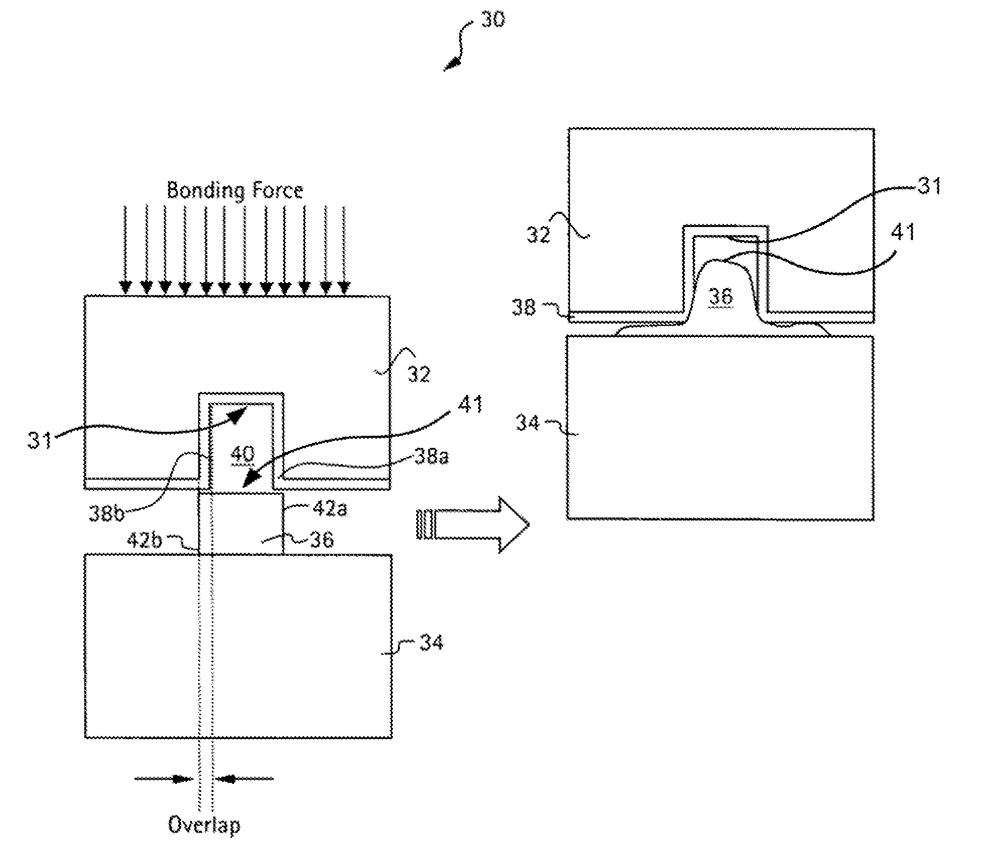
[0199]A hermetic seal was made using a tongue and groove joint design. The seal was made by a compression cold welding process. FIG. 3 shows an SEM of the seal. The substrates are silicon (top) and alumina (bottom). The metals are gold (sputtered on silicon, sputtered then electroplated on alumina). The parts were bonded on an FC-150 flip chip aligner, which is a machine that provides accurate alignment in x,y,z and pitch, roll, and yaw. Once the parts were aligned, the FC-150 compressed the parts together and the cold weld bond was formed.

example 2

Variation of Feature Sizes and Metal Thickness Impact on Hermeticity

[0200]Several different joint designs were fabricated, using different feature sizes and metal layer thicknesses. The joints were compression cold welded, and the sealed joints were tested for leaks using either a dye penetrant test or a He leak detector depending on the part geometry. As shown in Table 1 below, the seal integrity was found to be independent of feature size and gold metal layer thickness over the ranges tested. Undetectable leak rates may leak below the leak detectors lower limit or less than 5e-11 atm*cc / sec.

[0201]

TABLE 1Comparison of Various Joint Seals - Leak TestJointRidgeRidgeJointSurfaceGrooveWidthHeightstructureMetalGrooveGrooveMetal(188)(190)MaterialThicknessWidthDepthThicknessOverlapLeak TestResultsμmμm—μmμmμmμmμm——14550Gold—135501021DyeLeak Tightpenetrant5050Silicon7805072DyeLeak Tightpenetrant6050Gold—4650114He LeakUndetectable6050Gold—5350107He LeakUndetectable6050Gold—5050110He LeakUnde...

example 3

Array of Microfabricated Cavities Having Individual Seal Features

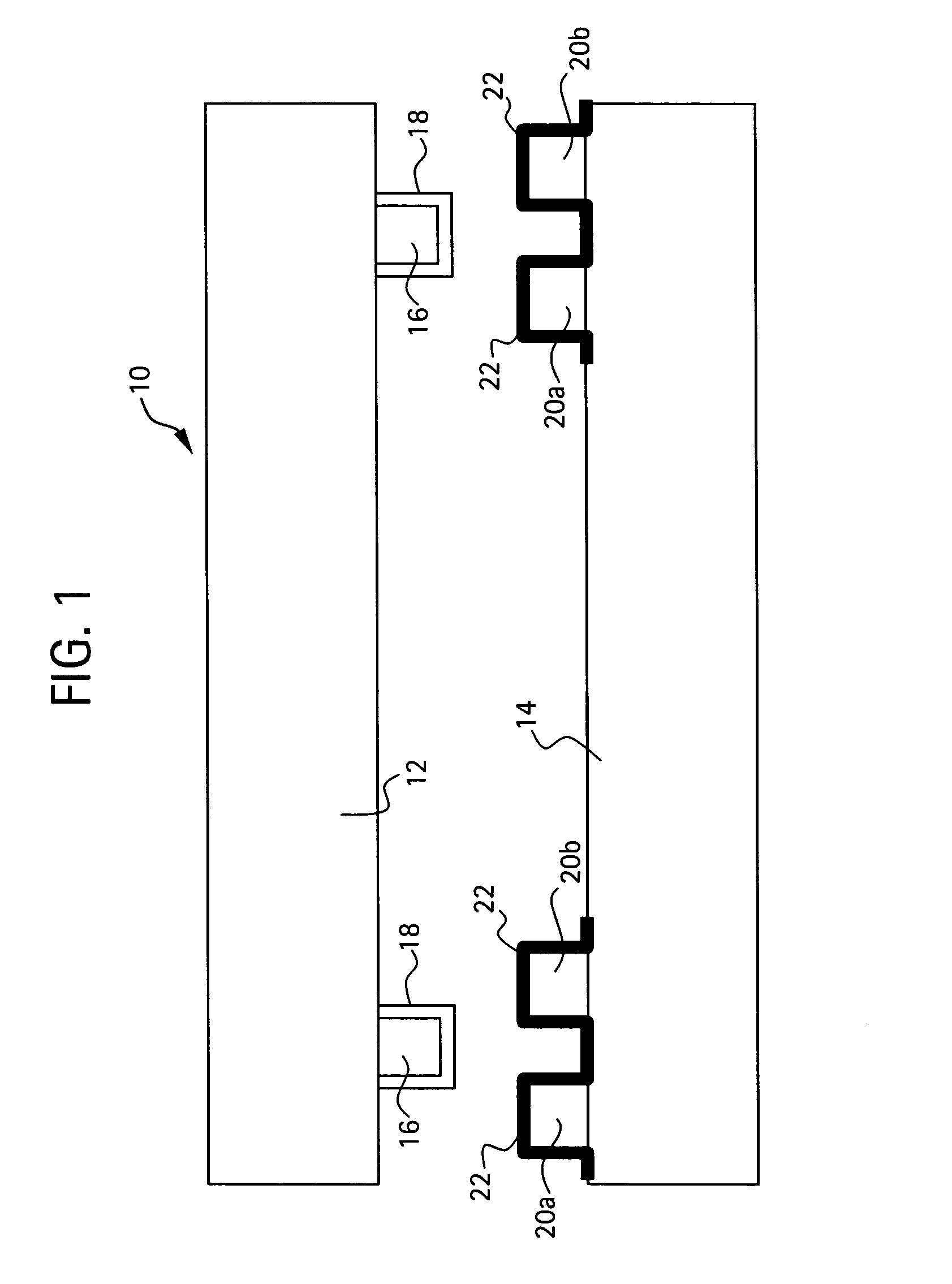
[0202]Two silicon substrates were provided made with complementary cavities and seal features for compression cold welding. The seal features included ridges that were microfabricated onto / into one substrate, and matching grooves that were microfabricated onto / into the other substrate. A shallow, wide cavity was formed inside each groove and inside each ridge. FIGS. 27A-B show the resulting substrates and seal features.


PUM

PropertyMeasurementUnit
widthaaaaaaaaaa
groove depthaaaaaaaaaa
heightaaaaaaaaaa

Abstract

Compression cold welding methods, joint structures, and hermetically sealed containment devices are provided. The method includes providing a first substrate having at least one first joint structure which comprises a first joining surface, which surface comprises a first metal; providing a second substrate having at least one second joint structure which comprises a second joining surface, which surface comprises a second metal; and compressing together the at least one first joint structure and the at least one second joint structure to locally deform and shear the joining surfaces at one or more interfaces in an amount effective to form a metal-to-metal bond between the first metal and second metal of the joining surfaces. Overlaps at the joining surfaces are effective to displace surface contaminants and facilitate intimate contact between the joining surfaces without heat input. Hermetically sealed devices can contain drug formulations, biosensors, or MEMS devices.

Description

CROSS-REFERENCE TO RELATED APPLICATIONS[0001]This application claims the benefit of U.S. Provisional Application No. 60 / 625,053, filed Nov. 4, 2004. The application is incorporated herein by reference in its entirety.BACKGROUND OF THE INVENTION[0002]This invention is generally in the field of methods and devices for sealing parts together, and more particularly hermetic sealing methods for devices and / or implantable medical devices.[0003]In many applications, there is a need to join, bond, or otherwise seal two or more parts together. Oftentimes, particularly with medical implant devices, these seals must be biocompatible and hermetic, for example, to protect the purity or quality of the reservoir contents.[0004]Examples of devices that may require sealing are described in U.S. Pat. Nos. 5,797,898, No. 6,527,762, No. 6,491,666, and No. 6,551,838, which are incorporated by reference herein. These devices for the controlled release or exposure of reservoir contents include a plurality...

Claims


Application Information

Patent Timeline
Patent Type & Authority Patents(United States)
IPC IPC(8): B23K20/12B23K31/00
CPCA61K9/0097B23K20/02B81C1/00047B81C1/00269F16B4/004F16B5/08F16B11/004H01L23/10H01L23/3142Y10T403/477A61M2205/0244A61M2207/00B81B2201/06B81C2203/0109B81C2203/019B81C2203/038H01L2224/16237H01L2224/81193H01L2924/01322A61M5/14276H01L2924/1461H01L2924/10253H01L2924/00B81C1/00095H01L2224/05568H01L2224/05023H01L2224/05001H01L2224/051H01L2224/056H01L2924/16315B33Y80/00H01L24/05H01L2924/00014B23K20/00
Inventor COPPETA, JONATHAN R.SHELTON, KURTSHEPPARD, JR., NORMAN F.SNELL, DOUGLASSANTINI, CATHERINE M. B.
Owner DARE MB INC
Learn More