
Lighting fixture with recessed baffle trim unit

a technology of recessed baffle and trim unit, which is applied in the direction of fixed installation, lighting and heating apparatus, lighting support devices, etc., can solve the problem of low profile of integrated baffle/heat sink, and achieve the effect of improving heat control and improving the grounding of the trim uni

Inactive Publication Date: 2012-05-22
CORDELIA LIGHTING
View PDF9 Cites 88 Cited by
  • Summary
  • Abstract
  • Description
  • Claims
  • Application Information

AI Technical Summary

Benefits of technology

"The present invention is a recessed lighting fixture that allows for aesthetically pleasing illumination when placed within a cavity of a surface. The fixture includes a recessed housing, a lighting trim unit, a light source, and a baffle with a low profile heat sink integrated with it. The baffle is in contact with the light source and directs the light from the fixture at the opening of the surface. The fixture also includes a spring that holds the trim unit in place and a tilting mechanism for adjusting the elevational aim of the light source. The technical effects of the invention include improved heat control, improved grounding, and aesthetically pleasing illumination."

Problems solved by technology

The sizes and number of baffle heat sink fins are selected to result in the integrated baffle / heat sink being low profile.

Method used


Image

  • Lighting fixture with recessed baffle trim unit
  • Lighting fixture with recessed baffle trim unit
  • Lighting fixture with recessed baffle trim unit

Examples


Embodiment Construction

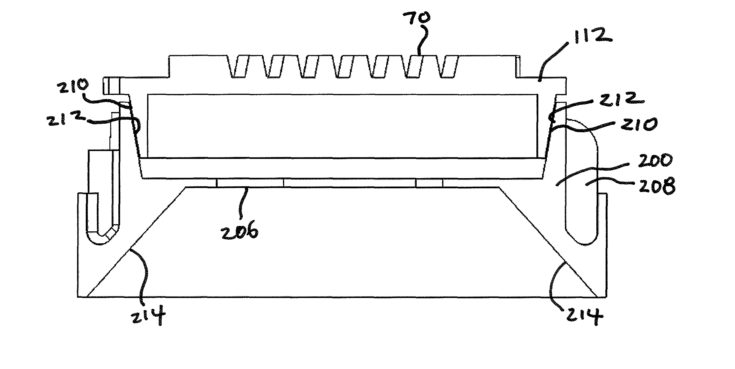
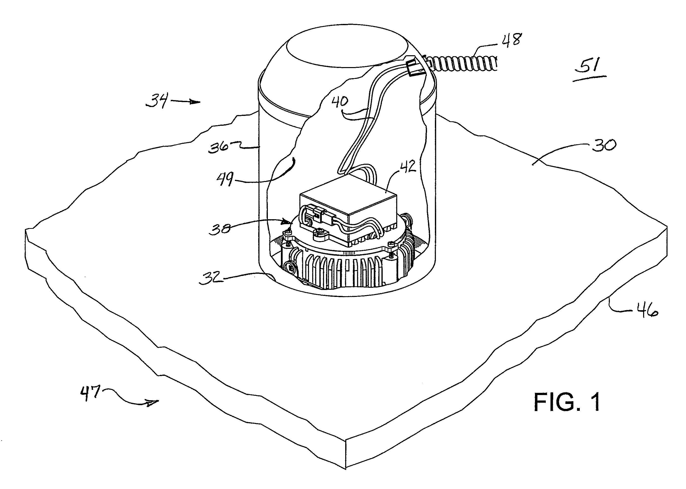
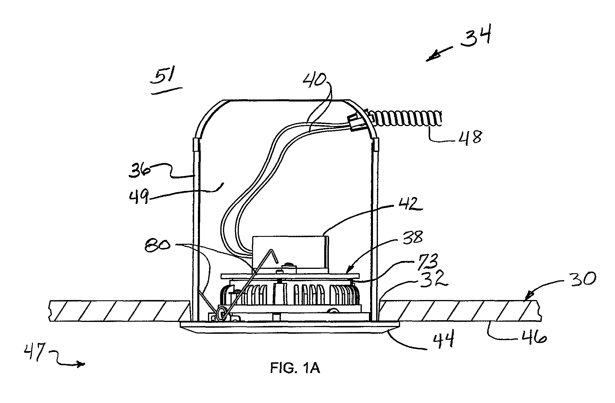
[0052]Referring now to the drawings in more detail in which like reference numerals refer to like or corresponding devices among the views, there is shown in FIGS. 1 and 1A a top perspective view and a side view, respectively, of a planar surface 30 having an opening 32 made to receive a recessed light fixture 34. Both figures show the recessed housing 36 or “can” of the light fixture and in cutaway views, a trim unit 38 mounted within the housing. Power wires 40 provide power to a drive unit 42 that provides power to the light sources (not shown). The trim unit includes a trim ring 44 located on the outer side 46 of the planar surface 30 that is larger than the opening 32 (shown in FIG. 1A). The trim ring 44 covers the opening and provides a stop surface for the trim unit 38 so that it cannot be recessed entirely into the opening. In the case where the planar surface 30 is a ceiling, the trim ring 44 is located within the room 47 of which the ceiling forms a part. As described belo...


PUM


Abstract

A recessed lighting fixture providing illumination from a light source including a plurality of light emitting diodes (LEDs) placed within a cavity of a planar surface, such as a ceiling, wall, or shower. The fixture comprises a baffle integrated with a low profile heat sink that is used to draw heat out of the fixture and communicate that heat to a trim ring of the fixture for dissipation of the heat in the room so that higher intensity light sources can be used. Improved grounding of the recessed trim unit to the recessed housing is provided with combination support and grounding springs. One embodiment of the light source is fixed in position while a second embodiment is gimbal mounted for aiming the light produced by the fixture.

Description

CROSS-REFERENCE TO RELATED APPLICATIONS[0001]This application is a continuation-in-part (CIP) of U.S. application Ser. No. 12 / 249,683, filed Oct. 10, 2008, now U.S. Pat. No. 7,722,227, which claims priority to U.S. Provisional Application No. 60 / 979,068, filed Oct. 10, 2007, and to U.S. Application No. 29 / 295,943 filed Oct. 10, 2007, now U.S. Pat. No. D595,452, all of which are incorporated herein by reference in their entireties.BACKGROUND[0002]The present invention relates generally to lighting fixtures and, more particularly, to a recessed lighting fixture that provides improved heat dissipation and grounding.[0003]Recessed lighting fixtures are well known in the art. Ideally, such fixtures are designed to be visually unobtrusive in that very little of the lighting fixture is visible from below the ceiling. However, some trim portions are visible as well as the light sources. An opening is cut into the ceiling into which most of the light fixture is mounted so that very little ex...

Claims


Application Information

Patent Timeline
Patent Type & Authority Patents(United States)
IPC IPC(8): F21V29/00
CPCF21V29/004F21S8/02F21S8/026F21V21/046F21V29/773F21V23/00F21V29/713F21V29/763F21V21/30
Inventor ZHANG, KANGHONGDIX, DAN
Owner CORDELIA LIGHTING
Learn More