
Ballistic shield

Inactive Publication Date: 2012-05-15
WRIGHT MATERIALS RES
View PDF8 Cites 47 Cited by
  • Summary
  • Abstract
  • Description
  • Claims
  • Application Information

AI Technical Summary

Benefits of technology

[0009]It is therefore an object of the present invention to provide a lightweight man-portable ballistic shield offering NIJ Level IV protection.
[0011]It is yet another object of the present invention to provide such a ballistic shield that permits through shield viewing in low light conditions without the intentional introduction of a lower threat level weakness in the shield.
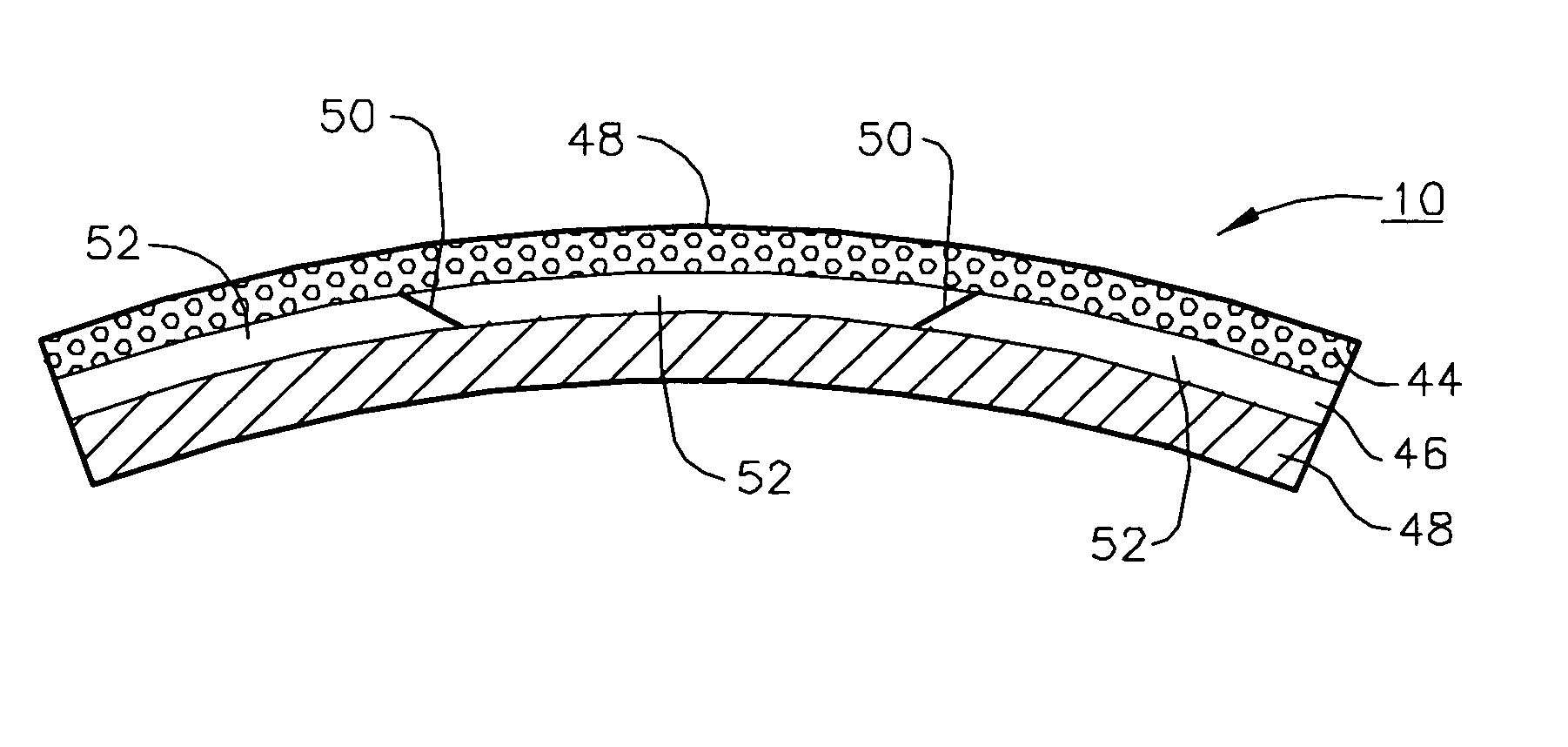
[0013]According to the present invention, there are provided a relatively light weight man-portable ballistic shield for ballistic protection up to mainly 7.62×63 mm AP rounds (NIJ Level IV) and a similar SAPI element. The ballistic shield and SAPI element are multi-layered and include polymer foam, ceramic tiles, and a support structure fabricated from ballistic resistant fabrics. Individual layers are bonded with adhesives and preferably wrapped with fabric. Under the fabric cover is a polymer foam layer that exhibits excellent blast impact resistance and blast attenuation properties. Although this foam layer can be manufactured from many kinds of polymers it is preferably made from liquid crystal or semi-crystalline polymer to enhance fire resistance and provide enhanced ductility. According to a preferred embodiment, the man-portable ballistic shield of the present invention also incorporates a compact video system for viewing the front side of the ballistic shield thereby allowing for the elimination of the transparent view port weakness of current state of the art ballistic shields.

Problems solved by technology

In recent years, the availability of higher powered rifles and a variety of small caliber AP rounds has posed additional threats for law enforcement officers as well as the military.
This weight severely affected the user's mobility and were basically unmanageable.
This state-of-the-art ballistic shield is still very heavy and therefore, is mounted on wheels or dolly for mobility.
It is, therefore, a major weakness in the state-of-the-art NIJ Level IV ballistic shield.
While this improves visibility, it does not eliminate the basic problem of the relatively poor ballistic protection offered by the transparent polycarbonate window.

Method used


Image

  • Ballistic shield
  • Ballistic shield
  • Ballistic shield

Examples


example 1

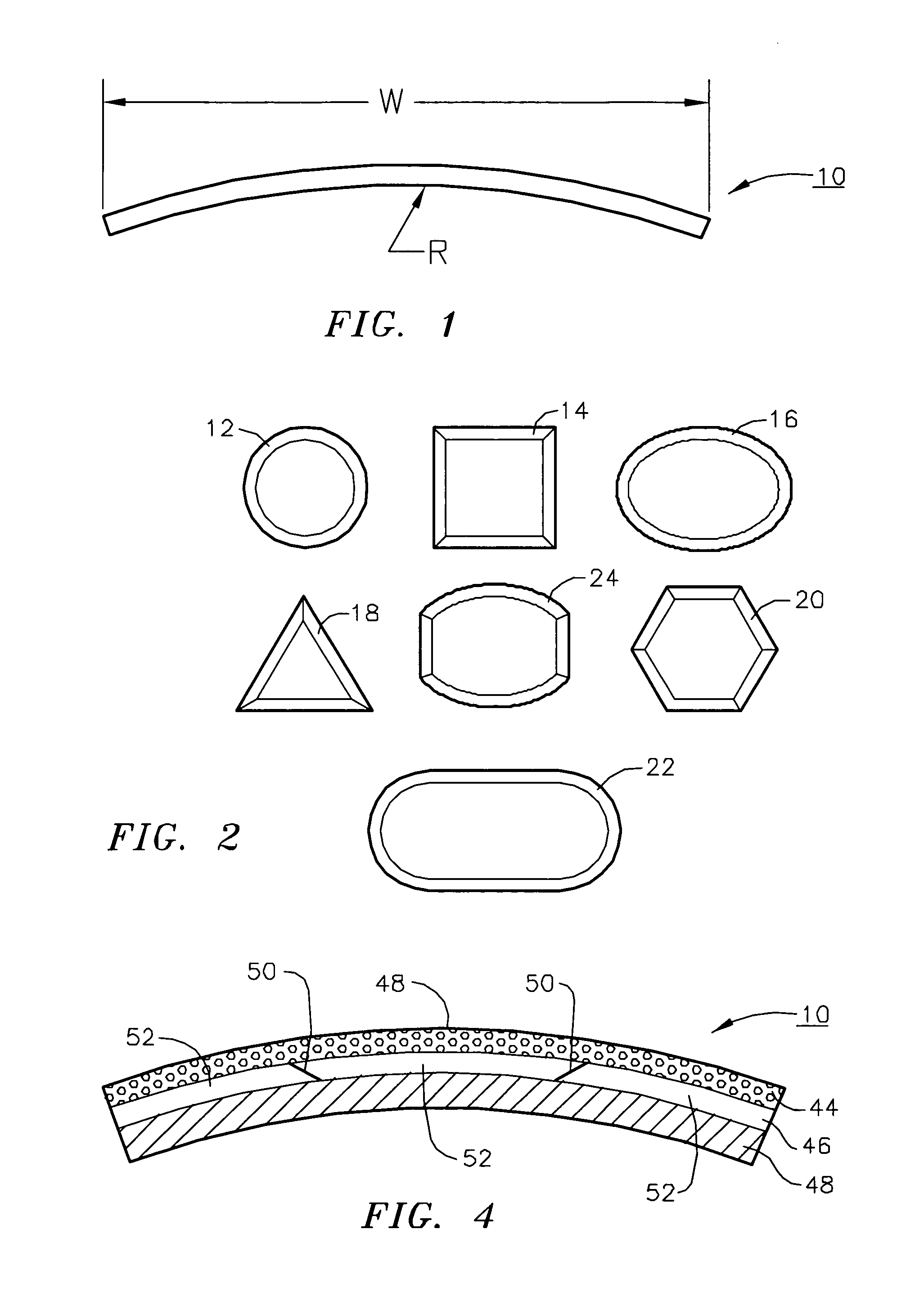
[0035]Spectra Shield® was purchased from Honeywell (101 Columbia Road, Morristown, N.J. 07962). Kevlar®, and Twaron® fabrics were purchased from Barrday, Inc. (75 Moorefield St., P.O. Box 790, Cambridge, ON N1R 5W6) and Hexcel Schwebel (2200 South Murray Ave., Anderson, S.C.). To fabricate the support structure with the single curvature as shown in FIGS. 1 and 4 we machined a closed mold from aluminum alloy. With a radius of curvature of 20-in and a projected width of 20-in the length of the curve is about 21-in. The height of the mold is 34-in. We first cut 28 layers of Spectra Shield and placed them into the mold. After closing the mold we heated the mold platens of a hydraulic press top to a temperature of between 120 and 150° C. and soaked for 10 to 60-min. The mold was then cooled down to a temperature somewhat below the molding point. The sample was removed from the mold. It has become a well-consolidated structure with a single curvature with a radius of curvature of 20-in. W...

example 2

[0036]A Xydar® (LCP) foam block was manufactured according to the process described in a co-pending U.S. patent application Ser. No. 11 / 807,488. It was sliced into thin sheets between 0.125 and 0.25-in thick.

[0037]Silicon carbide tiles were purchased from CoorsTek (600 9th Street, P.O. Box 4025, Golden, Colo. 80401). Three pieces of SiC tiles were manufactured to make up the sizes (20-in projected width and 34-in height) and shape (radius of curvature of 20-in) as shown in FIGS. 1 and 4.

[0038]Using a Spectra Shield® support structure molded as described in EXAMPLE 1 we bonded the SiC tiles and the support structure with a room temperature cured adhesive. It was a Loctite® 60-min cure adhesive produced by Henkel Corporation was used for bonding. After 60-min or longer of cure time the SiC tiles and the Spectra Shield support structure became an integrated structure. The thin sheet of Xydar® foam mentioned above was then bonded to this structure using a sprayed adhesive manufactured b...

example 3

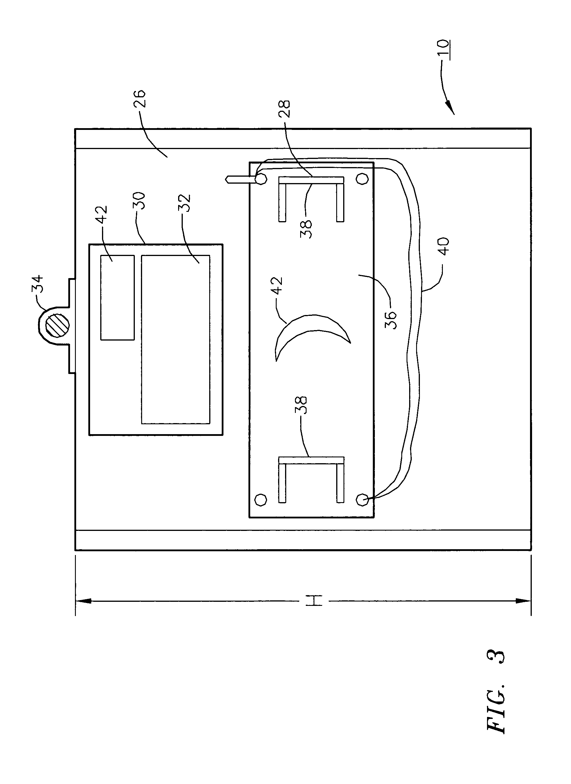
[0039]Two to eight holes were drilled along both sides of the support structure, prepared as described above, before it was bonded to the foam and ceramic plates. The holes were located near the center along the side of the shield. This allows the shield carrying plate 36 to be fastened at various locations and enable the user to conveniently cover the vital areas of his / her body according to his / her height. Tee nuts were installed at these holes. The shield carrying plate 36 is fastened to the shield using bolts through these holes with T nuts. This design does not create any holes in the hard layer and therefore eliminates all the weaknesses due to window and fastening that occur in the conventional ballistic shields.


PUM

PropertyMeasurementUnit
Temperatureaaaaaaaaaa

Abstract

A ballistic shield for protection against up to 7.62×63 mm AP rounds (NIJ Level IV). The ballistic shield is multiple layered and includes polymer foam, ceramic tiles, and a support structure fabricated from ballistic resistant fabric. Individual layers are bonded with adhesives and preferably wrapped with fabric. Under the fabric cover of the exterior surface of the shield is a polymer foam layer that exhibits excellent blast impact resistance and blast attenuation properties as well as a hard ceramic or the like layer. The foam layer is preferably made from liquid crystal or semi-crystalline polymer to enhance fire resistance and provide enhanced ductility. According to various preferred embodiments, the man-portable ballistic shield also incorporates a compact video system for viewing the front side of the ballistic shield to eliminate the transparent view port of current ballistic shields and protective foam about the periphery and on the rear surface thereof.

Description

[0001]The application is a continuation-in-part of U.S. patent application Ser. No. 12 / 586,568, filed Sep. 24, 2009FIELD OF THE INVENTION[0002]The present invention relates to ballistic shields and more particularly to such devices that are light enough to be readily man portable or to serve as protective inserts.BACKGROUND OF THE INVENTION[0003]Man portable ballistic shields are frequently used by SWAT teams, bomb squads, policemen, military agencies, and in civilian applications that may involve fragment impact due to operations related gun fire or explosions. Weight is a major consideration in the design of such portable shields. Most currently available ballistic shields are designed to defeat NIJ Level II and III rounds. Currently available ballistic shields for NIJ Level IV (7.62×63 mm AP (Armor Piercing)) protection are so heavy that they are mounted on wheels for mobility. In recent years, the availability of higher powered rifles and a variety of small caliber AP rounds has...

Claims


Application Information

Patent Timeline
IPC IPC(8): F41H5/02
CPCF41H5/0428F41H5/0492F41H5/08
Inventor TAN, SENG
Owner WRIGHT MATERIALS RES
Learn More