
LED lamp with flow guide function

a technology of led lamps and flow guides, which is applied in the direction of discharge tube main electrodes, semiconductor devices for light sources, lighting and heating apparatus, etc. it can solve the problems of easy heat aggregation, affecting the life and light emitting performance, and more waste heat produced, so as to reduce the overall temperature of led lamps and prevent a high temperature from affecting the use life and light emitting efficiency of led lamps. , the effect of increasing the airflow speed

Inactive Publication Date: 2012-04-24
GEM SUN TECH
View PDF14 Cites 56 Cited by
  • Summary
  • Abstract
  • Description
  • Claims
  • Application Information

AI Technical Summary

Benefits of technology

The solution effectively reduces the overall temperature of the LED lamp, preventing thermal aggregation and maintaining the lifespan and efficiency of the LEDs by accelerating heat dissipation through increased airflow.

Problems solved by technology

In general, the higher power of the LED results in more waste heat produced.
However, a high temperature has significant adverse effects on the life and light emitting performance of the LED, and thus the LED lamp with a higher power generally comes with a heat dissipating structure for dissipating heat of high temperature.
In the foregoing structure, although the heat dissipating area of the heat dissipating body can expedite the removal of the waste heat produced by the LEDs, yet the air flow speed of a natural convection is relatively slow, so that the heat dissipation process may still cause a heat aggregation easily, and the overall temperature of the LED lamp is relatively high, and thus affecting the using life and the light emitting efficiency of the LEDs.

Method used


Image

  • LED lamp with flow guide function
  • LED lamp with flow guide function
  • LED lamp with flow guide function

Examples


Embodiment Construction

[0014]The technical characteristics and contents of the present invention will become apparent with the following detailed description accompanied with related drawings, but the drawings are provided for reference and illustration of the invention only, but not intended for limiting the scope of the invention.

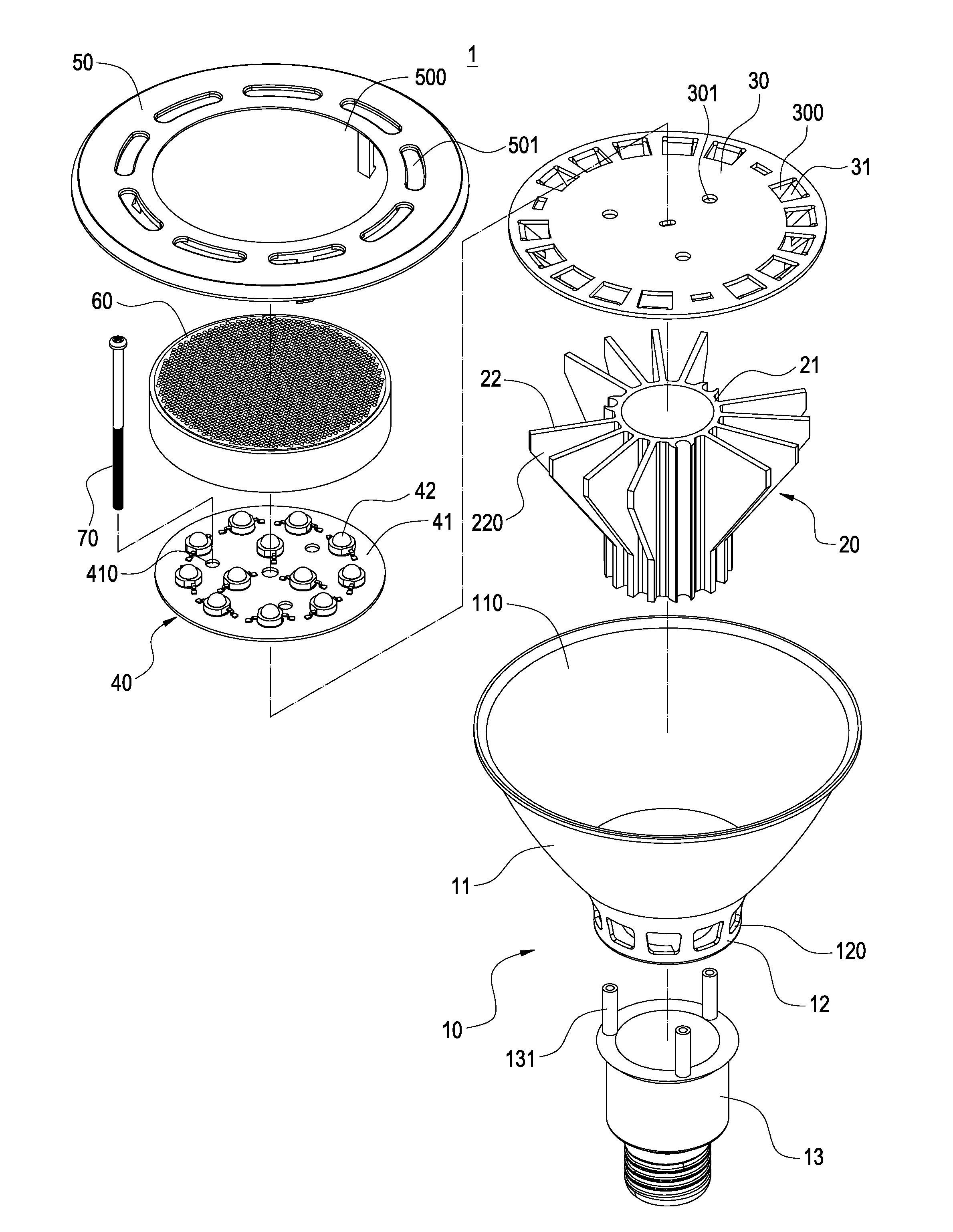
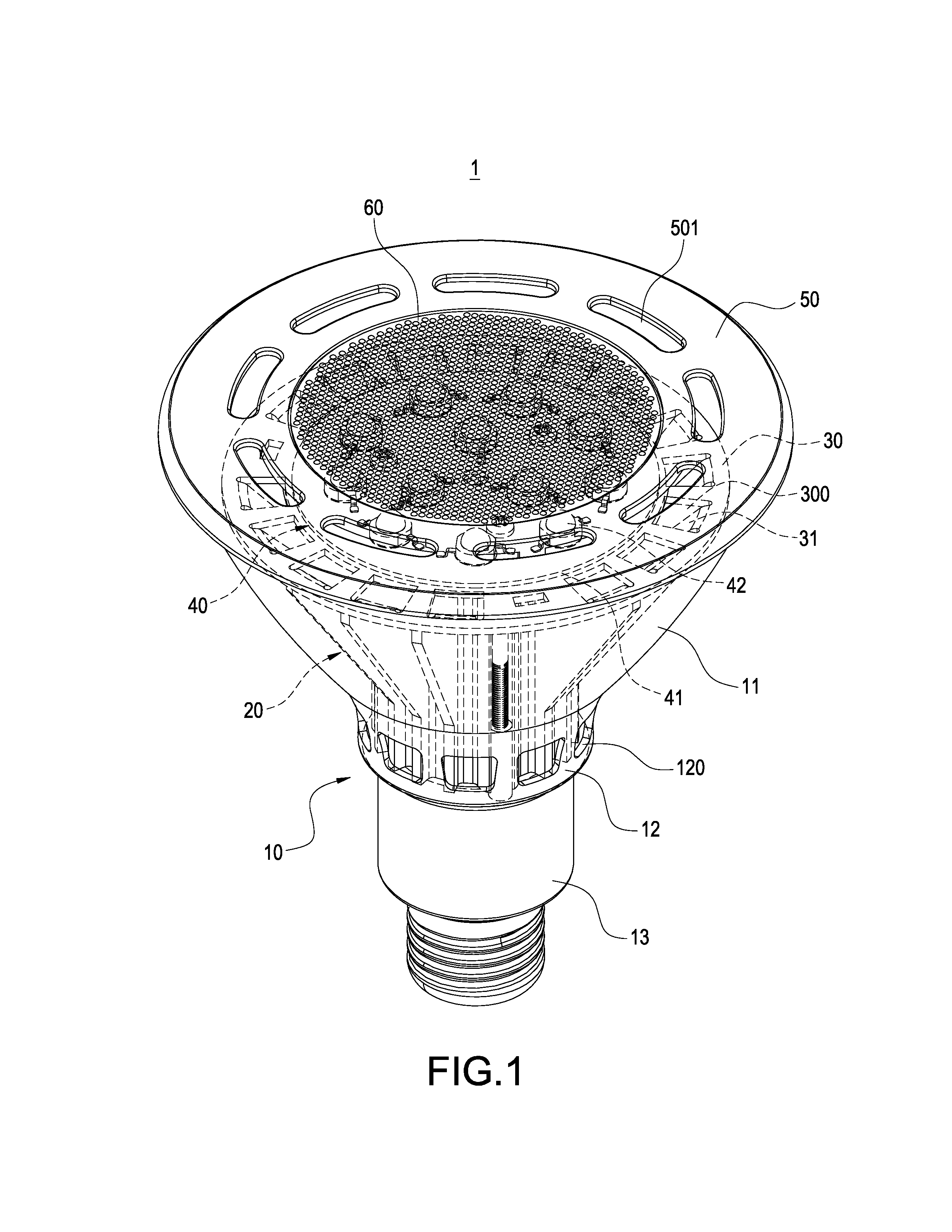
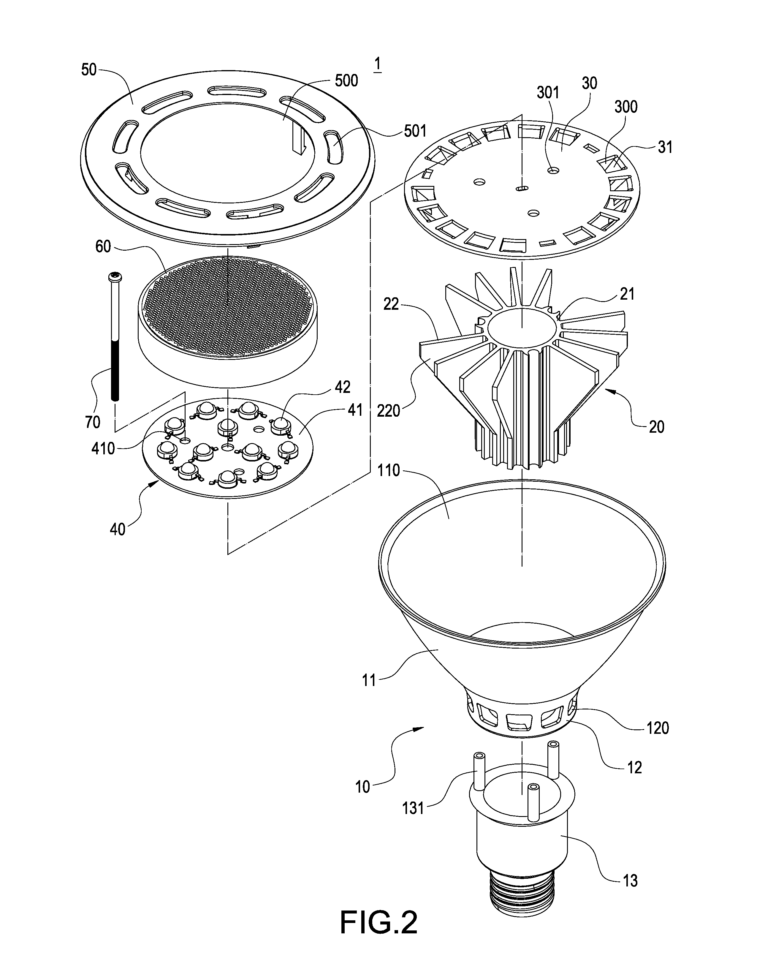
[0015]With reference to FIGS. 1 to 3 for a perspective view, an exploded view and a cross-sectional view of an LED lamp with a flow guide function in accordance with the present invention respectively, the LED lamp 1 comprises a lamp base 10, a heat dissipating body 20, a heat dissipating plate 30, an LED module 40, a cover 50 and a translucent lens 60.

[0016]The lamp base 10 includes a bowl-shaped lamp holder 11, a connecting section 12 extended from the bottom of the bowl-shaped lamp holder 11, and an electrically conductive connector 13. The bowl-shaped lamp holder 11 includes a containing space 110, a plurality of heat dissipating holes 120 formed on the connecting section 1...


PUM


Abstract

An LED lamp with a flow guide structure guides external air to dissipate heat from the LED lamp includes a lamp base, a heat dissipating body, a heat dissipating plate and an LED module installed in the lamp base, and heat dissipating holes formed on the lamp base. The heat dissipating body includes heat dissipating fins, and a heat dissipating passage defined between any two fins and disposed corresponding to the heat dissipating hole. The LED module is in a thermal contact with the heat dissipating plate. The heat dissipating plate is attached onto the heat dissipating fins and includes openings. A flow guide plate is formed at a lateral edge of each opening and extended from the heat dissipating plate for guiding external air into the heat dissipating passage and out from the heat dissipating hole to expedite a natural convection in the lamp and prevent a thermal aggregation.

Description

FIELD OF THE INVENTION[0001]The present invention generally relates to a light emitting diode (LED) lamp, in particular to an LED lamp with a heat dissipating structure.BACKGROUND OF THE INVENTION[0002]In recent years, the light emitting diode (LED) technology blooms and becomes well developed, and LED features a low power consumption, a long lifespan, a small volume and a quick response, and thus LED lamps have gradually replaced traditional halogen bulbs and become a mainstream market.[0003]In general, the higher power of the LED results in more waste heat produced. However, a high temperature has significant adverse effects on the life and light emitting performance of the LED, and thus the LED lamp with a higher power generally comes with a heat dissipating structure for dissipating heat of high temperature. The heat dissipating structure of a conventional LED lamp usually disperses waste heat from the LED lamp to the outside by convection, wherein a heat dissipating body is att...

Claims


Application Information

Patent Timeline
Patent Type & Authority Patents(United States)
IPC IPC(8): F21V29/02H01J61/52
CPCF21V29/75F21V29/83Y10S362/80F21Y2115/10F21Y2105/10
Inventor WEN, FONG-YUAN
Owner GEM SUN TECH
Learn More