Casing for fuel battery and fuel battery using the same

a fuel battery and casing technology, applied in the direction of cell components, superimposed coating process, cell component details, etc., can solve the problems of increasing the power consumption of the device, fuel cells using pefc are not suitable as power supplies for electronic devices, fuel cells are also not suitable as power supplies for portable devices, etc., to prevent corrosion and discoloration of the casing, prevent corrosion and discoloration, and easy to suffer from corrosion

Inactive Publication Date: 2012-02-21
HITACHI METALS LTD
View PDF17 Cites 0 Cited by
  • Summary
  • Abstract
  • Description
  • Claims
  • Application Information

AI Technical Summary

Benefits of technology

[0034]As mentioned above, the casing for a fuel cell according to the present invention is made of a magnesium alloy, and thus can apply appropriate pressing force to an MEA and a current collector without increasing the thickness of the casing while the portability (being thin and lightweight) of compact and portable electronic devices is not impaired. Although the magnesium alloy is a highly reactive material and easily suffered from corrosion, the coating with high corrosion resistance can prevent corrosion and discoloration of the casing even when formic acid at high concentration is produced in the DMFC.

Problems solved by technology

However, portable electronic devices are dramatically gaining more functions and higher performance, thereby increasing the power consumption of the devices.
However, the fuel cells using PEFC are not suitable as the power supplies for electronic devices such as compact and portable devices because the cells have problems such as requiring upgrading of infrastructure for providing hydrogen gas fuel, and having low energy densities per unit volume of hydrogen gas.
However, such a fuel cell is also not suitable as the power supplies for portable devices and the like because the fuel cell requires a reforming device besides the fuel cell itself.
The active mode has advantages such as enabling high power output by providing air, and enabling use of high concentration methanol fuel by circulating water produced at the cathode, whereas the mode has disadvantages of the difficulty of achieving size reduction because an auxiliary machine is required for providing fuel, and electric power consumption by the auxiliary machine.
The passive mode has an advantage of being suitable for achieving size reduction, whereas the mode has a disadvantage of being difficult to obtain high power output because providing fuel tends to become a rate-determining step.
As mentioned above, the passive type fuel cell is suitable for size reduction whereas providing fuel tends to become a rate-determining step and it is difficult to obtain high power output.
When such a fuel cell has a membrane and electrode assembly with large area which assembly comprises a proton exchange membrane, a hydrogen electrode, and an oxygen electrode which membrane is interposed between the electrodes, shape irregularities such as warp or waviness tend to occur on the sheet-like membrane and electrode assembly because of low processing accuracy, and which results in problems such as being incapable of achieving uniform contact between the membrane and electrode assembly and a current collector.
As a result, fuel cells with large areas have a problem of low current collecting efficiency, which means that the ratio of electric power that can be extracted via a current collecting plate with respect to electric power actually produced in the membrane and electrode assembly becomes low.
A casing made of metallic material obviously causes the problem of corrosion.
As a result, a casing made of resin material has large thickness and heavy weight, and such a casing is difficult to employ for a power supply mounted on compact and portable electronic devices and the like.

Method used


Image

  • Casing for fuel battery and fuel battery using the same
  • Casing for fuel battery and fuel battery using the same
  • Casing for fuel battery and fuel battery using the same

Examples


example 2

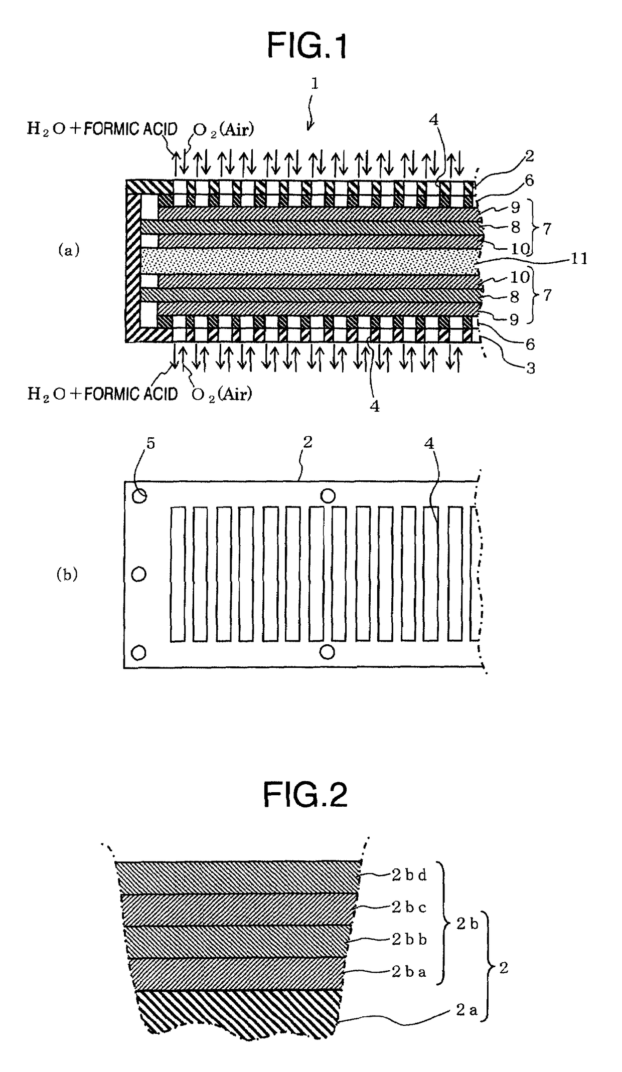
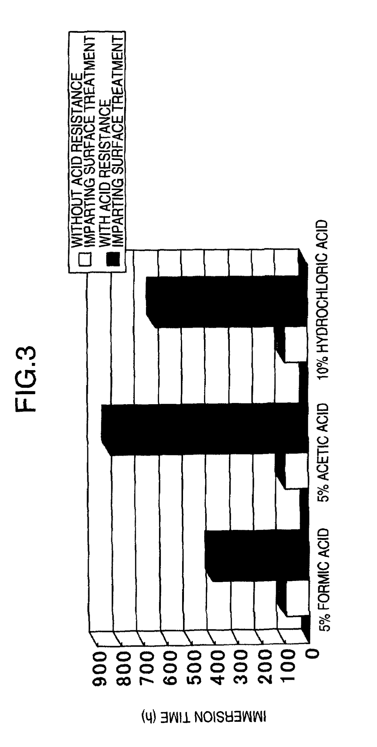
[0049]Next, the coating was improved for the purpose of increasing its corrosion resistance to each of the solutions of 5% formic acid, 5% acetic acid, and 10% hydrochloric acid. As a result of investigation, it was found that the corrosion and the discoloration are caused because aluminum flakes contained in a coating material for forming an overcoating layer (color coating) react with the immersion solutions. DMFCs are mounted on compact and portable devices, and DMFCs preferably have metallic appearances similar to the appearances of the devices in terms of design. To impart metallic appearances to DMFC casings, metallic particles such as aluminum flakes are added to coating materials used for color coating.

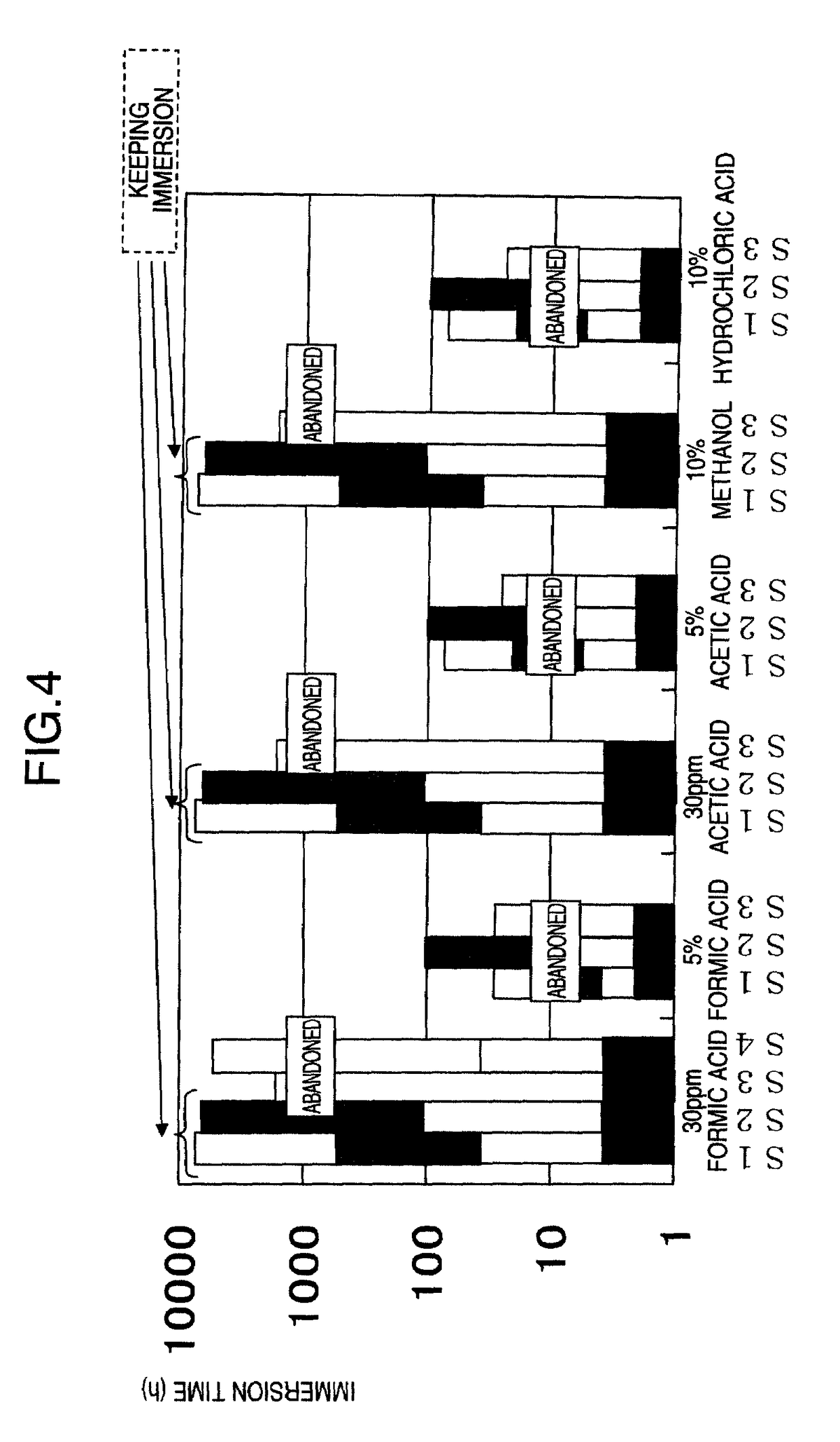
[0050]In Example 2, a coating was prepared to have the configuration of experimental sample S2: (a)+(b) 20 μm+(c) 20 μm where the (c) overcoating layer was formed by using HALS hybrid resin baking type coating material (base compound name: Acryo #BK6500). The base compound is ...

example 3

[0073]Hereinafter, there is described an example according to the present invention. By using the production method described so far, a magnesium alloy member was produced by subjecting a Mg alloy to the steps up to the Al plating step and the heat treatment step. The magnesium alloy member and comparative example magnesium alloy members having similar structures were compared in respect to generation of the separation between the layers and corrosion resistance to corrosive solutions.

[0074]The separation (adhesion) was evaluated as follows: slits were made with 1.5 mm pitches on the surface of an evaluation sample (magnesium alloy member) to form 10×10 squares by using a cutter; cellophane tape was affixed to the squares; when the tape was removed, a square where separation occurs in 80% or more of the square area was defined as a “separated square”; the number of the “separated square” was counted; based on the result, the ratio of squares other than the “separated squares” was de...


PUM

PropertyMeasurementUnit
temperatureaaaaaaaaaa
thicknessaaaaaaaaaa
thicknessaaaaaaaaaa

Abstract

This invention provides a casing for storing MEA, which has satisfactory corrosion resistance to formic acid produced in an electrode reaction of MEA. There is also provided a casing formed of a material having the lowest possible specific gravity that can apply a suitable pushing pressure to MEA and a current collector without increasing the thickness dimension and is suitable for a power supply mounted, for example, in small portable electronic equipment. The casing is a casing for use in a fuel battery in which a hydrogen electrode, an oxygen electrode, and a film-electrode joint product formed of a proton conductive film held between the hydrogen electrode and the oxygen electrode are housed within the casing and, in removing water produced in an oxygen electrode reaction, the above water comes into contact with the casing. The casing for a fuel battery comprises a base material (2a) formed of a magnesium alloy and a film (2b) provided on the base material (2a). The film (2b) comprises a conversion treated film (2ba), an undercoating layer (2bb), and a top coating layer (2bd) provided in that order from the base material side.

Description

[0001]This application is a 371 of PCT / JP2006 / 318350 filed Sep. 15, 2006 claiming the priority of JP2005-270435 filed Sep. 16, 2005 and JP2005-372371 filed Dec. 26, 2005, all of which are hereby incorporated by reference.TECHNICAL FIELD[0002]The present invention relates to a casing for a liquid fuel cell producing electricity by using liquid fuel such as methanol which casing contains electrodes, a proton exchange membrane, and the like; and a fuel cell including the casing.BACKGROUND ART[0003]In recent years, in the field of electronic devices, there have been rapid developments of compact and portable electronic devices represented by mobile phones and personal digital assistants according to technical advances. Under the circumstances, there is a need for batteries for such electronic devices which batteries are compact and usable for a long time. As for such batteries, there is an industry-wide shift from conventional single-use primary batteries to secondary batteries, which c...

Claims


Application Information

Patent Timeline
Patent Type & Authority Patents(United States)
IPC IPC(8): H01M2/00
CPCH01M8/04156H01M8/1002C23C28/00H01M8/0297C23C28/322C23C28/3225C23C28/345H01M2008/1095Y02E60/521H01M8/1007Y02E60/50
Inventor YAMAGUCHI, HIDEHISAKAWAUCHI, YUJIANDOH, SETSUO
Owner HITACHI METALS LTD
Why Eureka
Try Eureka