
Mixer circuit, integrated circuit device and radio frequency communication unit

a technology of integrated circuit and mixer circuit, which is applied in the direction of frequency-changer modification, transmission, electrical equipment, etc., can solve the problems of less than ideal linearity requirements for mixer circuits, less risk of noise pick-up, and limited number of circuit techniques that may be used

Active Publication Date: 2012-02-07
MEDIATEK SINGAPORE PTE LTD SINGAPORE
View PDF10 Cites 14 Cited by
  • Summary
  • Abstract
  • Description
  • Claims
  • Application Information

AI Technical Summary

Benefits of technology

The invention provides an improved mixer circuit for an integrated circuit device that overcomes the disadvantages of previous mixer circuits. The mixer circuit includes an input stage and a frequency conversion stage. The input stage converts an input voltage signal into a current signal, while the frequency conversion stage converts a current signal to an output frequency. The input stage has a resistance connected to the frequency conversion stage, which reduces the impact of inductors on the system and allows for better scalability. The mixer circuit can be used in a larger on-chip system without impacting the overall performance. The invention also provides an integrated circuit device comprising the improved mixer circuit.

Problems solved by technology

However, due to the high operating frequencies and the low signal levels of the received RF signal, only a very limited number of circuit techniques may be used to successfully implement the front-end circuitry that comprises the LNA circuitry and the mixer circuit.
However, fully integrated LNAs are known to exhibit poor selectivity.
Accordingly, the higher the LNA gain, the more challenging become the linearity requirements for the mixer circuit.
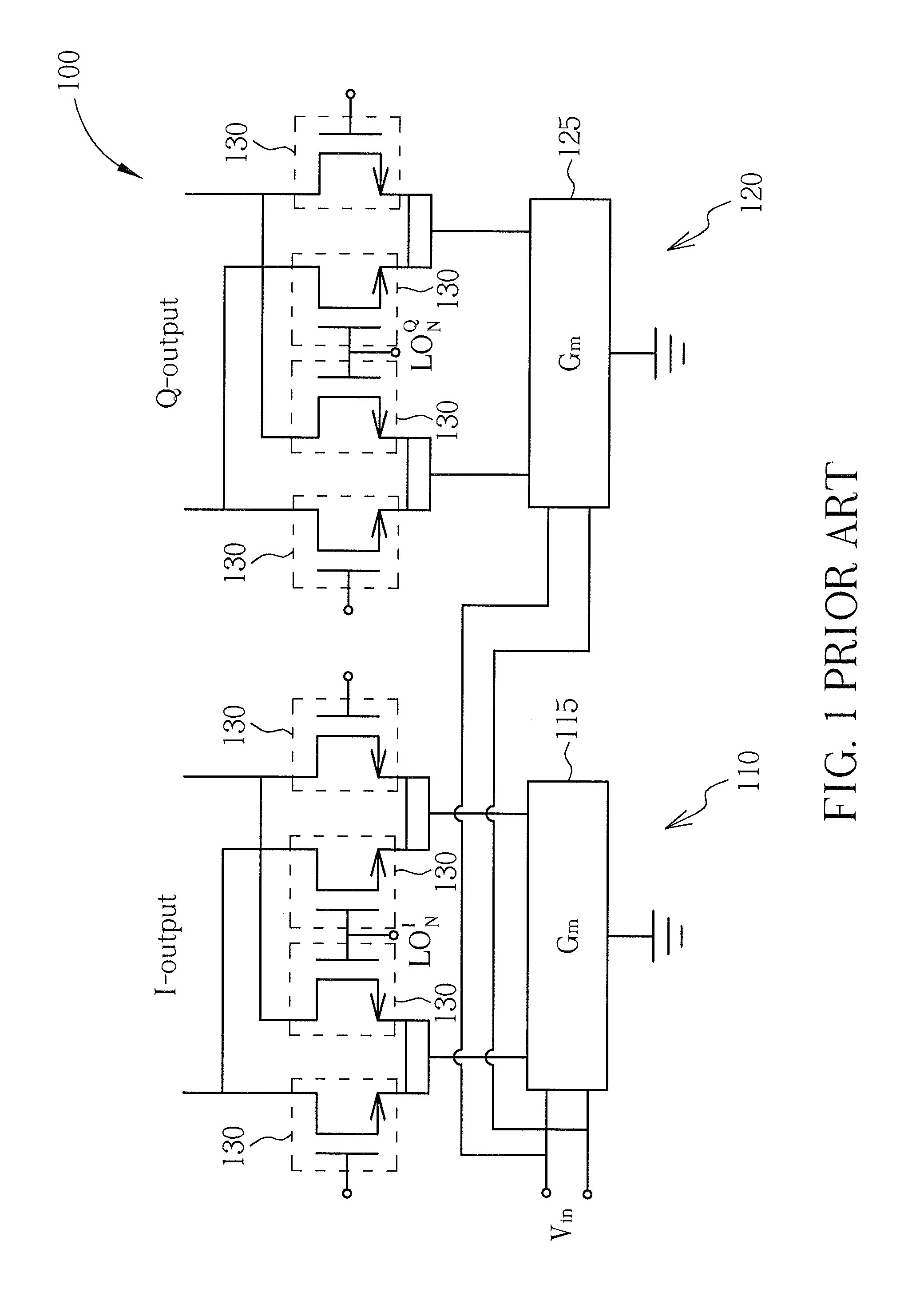
Two significant limitations of this known mixer design are firstly that the linearity of the mixer is primarily limited by the input transconductance stages 115, 125, and secondly that flicker noise generated by the transistors 130 appears at the output.
Such a stringent requirement is not achievable with the use of such an input transconductance stage.
As for the second of the above identified limitations, such a limitation is usually not significant for bipolar transistor implementations, since flicker noise is significantly less for bipolar transistors than it is for, say, MOSFETs (metal oxide semiconductor field effect transistors).
However, the presence of flicker noise at the output is a significant problem for CMOS implementations.
Whilst bipolar transistors may be more suitable for implementing mixer circuits in terms of their flicker noise, the fabrication of high performance bipolar transistors requires expensive processing steps during their fabrication.
Consequently, the fabrication of such high performance bipolar transistors is prohibitively expensive for cost sensitive implementations, such as within front end circuits of RF communication receivers.
However, such lower performance bipolar transistors are not capable of operating at the Gigahertz frequencies required by modern RF communication receivers.
However, since such a mixer design still comprises input transconductance stages 210, 220, the problem of odd-order distortion, and thus poor linearity, is still present.
However, once again the mixer circuit 300 still comprises input transconductance stage 310, and thus the problem of odd-order distortion, and thus poor linearity, is still present.
A problem with the mixer circuit 400 of FIG. 4 is that the LC tank 420 requires the inclusion of an inductor.
Analogue circuits comprising components such as inductors do not scale with improvements in semiconductor manufacturing processes in the same manner as digital circuits.
Thus, the presence of analogue components, such as inductors, is a considerable burden on the ability to scale a circuit in order to reduce the size, footprint, etc. of an integrated circuit device.

Method used


Image

  • Mixer circuit, integrated circuit device and radio frequency communication unit
  • Mixer circuit, integrated circuit device and radio frequency communication unit
  • Mixer circuit, integrated circuit device and radio frequency communication unit

Examples


Embodiment Construction

[0038]Examples of the invention will be described in terms of a radio frequency (RF) communication receiver front-end mixer circuit. However, it will be appreciated by a skilled artisan that the inventive concept herein described may be embodied in any type of mixer circuit. In a number of applications, a mixer circuit adapted in accordance with the hereinafter described examples may effectively perform frequency translation of a received signal, without distortion that would typically be introduced by, say, a transconductance input stage, and without the need for on-chip inductor coils or the like. In this manner, such a mixer circuit may comprise improved scalability, and may provide lower and well defined impedances at interfaces between itself and other integrated on-chip sub-blocks, such as a preceding low noise amplifier sub-block.

[0039]Referring first to FIG. 5, a block diagram of an example of a radio frequency (RF) communication unit (sometimes referred to as a mobile subsc...


PUM


Abstract

A mixer circuit comprises an input stage arranged to convert an input voltage signal received at an input of the mixer circuit into at least one current signal, and a frequency conversion stage comprising at least one switching element arranged to convert a signal component of the at least one current signal from an input frequency to a output frequency. The input stage comprises at least one resistance connected between the input of the mixer circuit and the at least one switching element. The at least one switching element and the at least one resistance are arranged such that the at least one switching element comprises a ‘turn-on’ resistance that exhibits a resistivity that is a factor less than the at least one resistance connected thereto.

Description

FIELD OF THE INVENTION[0001]The field of this invention relates to a mixer circuit, an integrated circuit device and a radio frequency communication unit comprising such a mixer circuit and / or integrated circuit. The invention is particularly applicable to, but not limited to, an integrated, linear, inductor-less mixer circuit.BACKGROUND OF THE INVENTION[0002]In the field of radio frequency (RF) communication receivers, the main task of the receiver front-end circuit is to process a signal that is received by an antenna coupled to the receiver front-end circuit in such a manner that it can be more easily processed by subsequent receiver circuits, for example, demodulation circuitry. Typically, such front-end circuits comprise low noise amplifier (LNA) circuitry for amplifying the received RF signal, and mixer circuit arranged to perform frequency translation of the amplified radio frequency signal to a lower intermediate or baseband frequency. The intermediate / baseband frequency sig...

Claims


Application Information

Patent Timeline
Patent Type & Authority Patents(United States)
IPC IPC(8): H04B1/26
CPCH03D7/165H03D7/18
Inventor BEFFA, FEDERICO ALESSANDRO FABRIZIO
Owner MEDIATEK SINGAPORE PTE LTD SINGAPORE
Learn More