System, apparatus, and method for viewing a visually obscured portion of a cavity

a technology of visual obscurement and cavity, applied in the field of exploratory instruments, can solve the problems of large diameter of endoscope, many design and functionality limitations that do not facilitate diagnosis and surgery, and the risk of missing some pathology during diagnosis, so as to prevent the impact of foreign matter

Active Publication Date: 2011-12-13
CAMPOS
View PDF59 Cites 104 Cited by
  • Summary
  • Abstract
  • Description
  • Claims
  • Application Information

AI Technical Summary

Benefits of technology

[0019]Another feature of this aspect of the invention is that the endoscope system may include a working channel extension, associated with the face tip assembly, which includes at least one protrusion adapted to guide the working instrument and to prevent impact of foreign matter located within the body cavity upon the at least one optical collector. An additional feature of this aspect of the present invention is that there may be two optical conductors for producing a three-dimensional image. A further feature of this aspect of the present invention is that the actively flexible shaft segment may be disposed adjacent a passively flexible shaft segment. An additional feature is that the passively flexible shaft segment may be disposed adjacent a semi-rigid shaft segment.
[0021]An additional feature of this aspect of the present invention is that the endoscope may include a working channel extension associated with the face tip assembly, which includes at least one protrusion to guide the working instrument and to prevent impact of foreign matter upon the at least one optical image collector. A further feature of this aspect of the present invention is that the shaft assembly may have a longitudinal axis and the at least one optical image collector may lie in a first plane which is disposed substantially perpendicular to the longitudinal axis of the shaft assembly; and the at least one protrusion is disposed at the distal end of the shaft forward of the first plane in which the at least one optical image collector lies, whereby the at least one optical image collector may view an operating tool passing forwardly beyond the at least one protrusion.

Problems solved by technology

During this time, the endoscopes were substantially rigid and their diameters were rather large, which had several limitations when entering and exploring a soft and curved conduit, such as the ureter.
These endoscopic type instruments, however, had many design and functionality limitations that do not facilitate diagnosis and surgery of body cavities, such as those in the upper urinary system.
For example, rigid and semi-rigid endoscopes could not explore the upper urinary system within the kidney, thus, there was a risk of missing some pathology during diagnosis that might not be apparent by other imaging techniques such as x-rays, MRI, and CT scans, etc.
Also, rigid and semi-rigid endoscopes were further inherently limited when performing surgical procedures that require flexibility.
The rigid, or even the semi-rigid, endoscopes do not permit exploration and intervention of the upper urinary tract within the kidney due to their inherent lack of adaptability and flexibility.
For example, use of a rigid endoscope required penetration of the kidney during examination, or if entrance through the natural channels, then excessive rotation and maneuvering of the device is required, whereas the flexible endoscope has the versatility to maneuver through the urinary tract and directly into the kidney.
Specifically, the rigid and semi-rigid endoscopes cannot properly explore the upper urinary system within the kidney; thus a diagnosis might be missed.
Flexible endoscopes, however, are typically very difficult to use since their flexibility makes insertion of the instrument difficult, and proper use in such anatomical sections such as the upper urinary system is beyond the typical user's experience level.
Most urologists do not have the skill, sensitivity, dexterity, or expertise to operate with fully flexible endoscopes.
Fully flexible endoscopic type instruments are difficult to insert due to their lower consistency and firmness because they are typically made from a soft plastic, or polymer like material formed around the fiber optics, which material bends easily.
The instrument's excessive flexibility makes handling difficult and often results in the need for an extra pair of trained hands, such as those of a nurse or physician, for its introduction.
The surgeon's lack of view of the natural curves of the ureter, caused by the blind spot, can produce an inadvertent tear or perforation of the ureteral wall.
This maneuver, or “frequent rotation” may increase the risk of perforation and / or the inherent trauma by the instrument's insertion or pressure creating inflammation of the structures under exploration.
Endoscopic type instruments have typically ranged in complexity from simple viewing scopes which employ a light source and an ocular system, to relatively complex instruments having a light source, an image collection system, fluid channels, and a surgical or working tool channel.
This often results in a lack of depth perception for the user of the instrument, making it difficult to perform an accurate inspection or surgery.
Although, three-dimensional, or stereoscopic, laproscopic type instruments, such as steromicroscopes, have been developed for creating a three-dimensional view of the object or region under inspection these are not suited for use in endoscopics.
Although the human brain can converge and “fuse” two separate views if the separation between the images is not too great, this is not easy or comfortable to achieve in practice.
However, this is not a practical solution in endoscopic type systems where the necessary convergence at very short focal lengths is compounded by the need to keep the overall diameter of the system as small as possible so that the endoscope tube can be inserted through a single minimum size surgical incision, minimizing invasive procedures.

Method used


Image

  • System, apparatus, and method for viewing a visually obscured portion of a cavity
  • System, apparatus, and method for viewing a visually obscured portion of a cavity
  • System, apparatus, and method for viewing a visually obscured portion of a cavity

Examples


Embodiment Construction

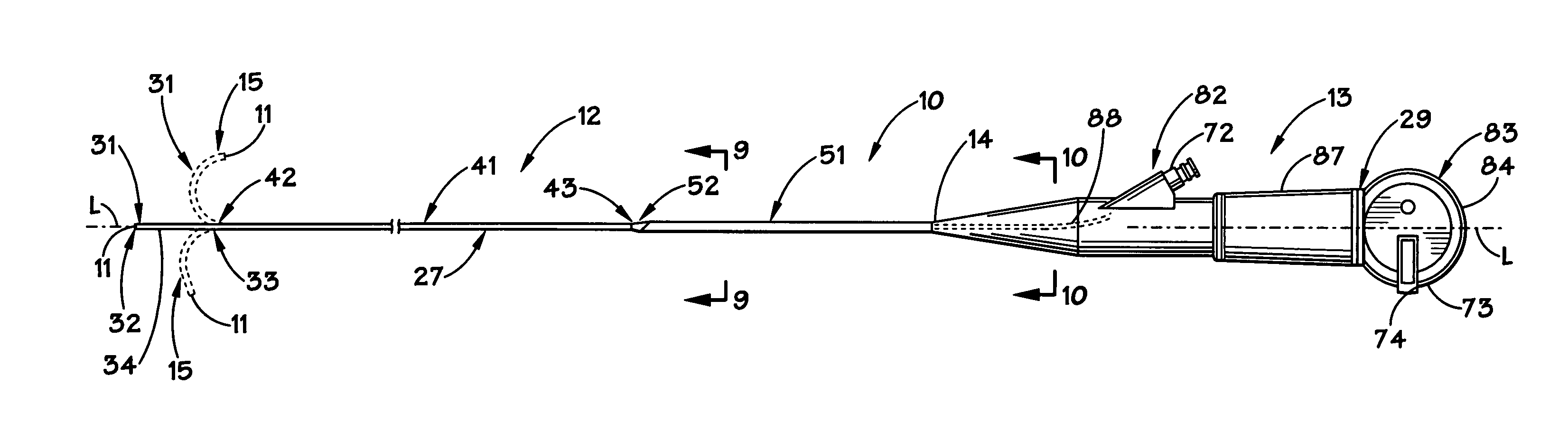
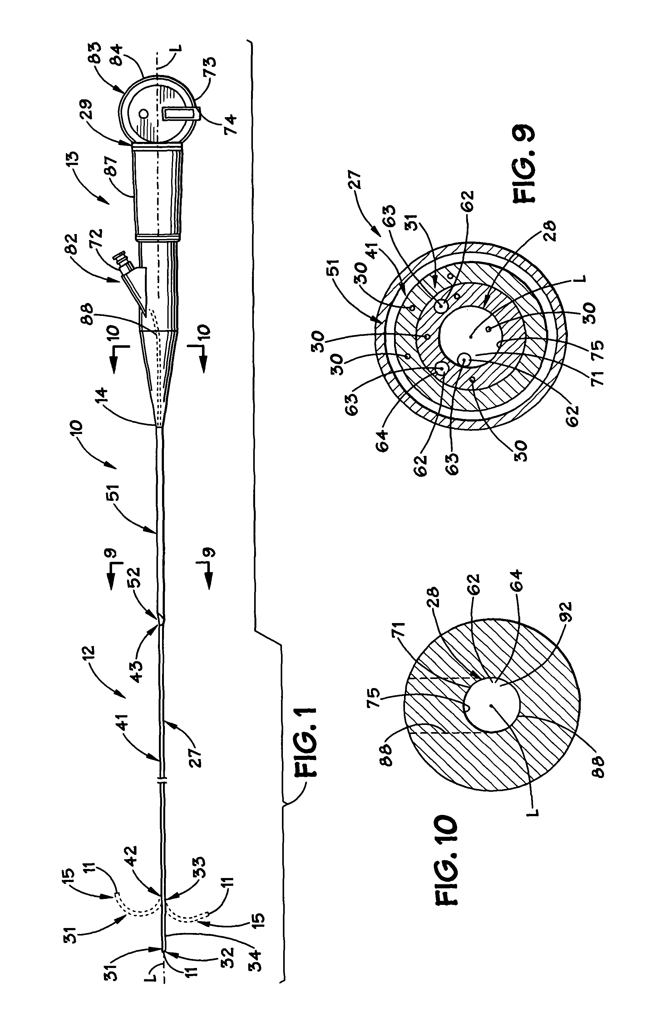
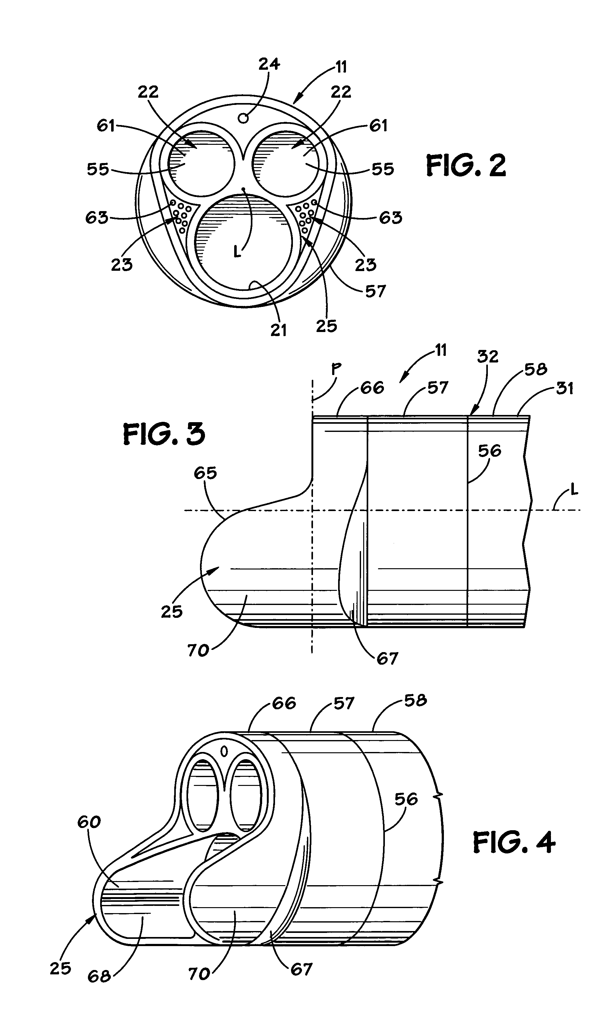
[0036]The present invention will now be described more fully hereinafter with reference to the accompanying drawings which illustrate embodiments of the invention. This invention may, however, be embodied in many different forms and should not be construed as limited to the illustrated embodiments set forth herein. Rather, these embodiments are provided so that this disclosure will be thorough and complete, and will fully convey the scope of the invention to those skilled in the art. Like reference numbers refer to like elements throughout, and the prime notation, if used, indicates similar elements in alternative embodiments. The preferred embodiment of the present invention implements an endoscopic type instrument, or endoscope, which may be in the form of a ureteroscope.

[0037]Referring now to the drawings, a first embodiment of the present invention in the form of a ureteroscope 10 is illustrated in FIGS. 1-4. This ureteroscope 10 is only one of many variations of endoscopes, or ...


PUM


Abstract

A system, apparatus, and method for viewing a visually obscured portion of a body cavity. The system includes an endoscopic-type instrument, an imaging apparatus, and a human interface apparatus. The endoscopic-type instrument includes a face tip assembly connected to a shaft assembly, the shaft assembly being connected to a handle and viewing assembly. The face tip assembly includes a plurality of input / output ports and a working channel extension to protect an optical image collector. The shaft assembly includes an actively flexible shaft segment and a passively flexible shaft. The method for viewing a visually obscured portion of a cavity includes the steps of providing an instrument having an actively flexible shaft segment and manipulating the actively flexible shaft segment to a desired angular deflection.

Description

RELATED APPLICATIONS[0001]This application claims the benefit of U.S. Provisional Patent Application Ser. No. 60 / 464,602, filed Apr. 22, 2003.BACKGROUND OF THE INVENTION[0002]1. Field of the Invention[0003]The invention relates to exploratory instruments and, more particularly, to endoscopic type instruments.[0004]2. Description of the Related Art[0005]Endoscopic type instruments have been developed to allow physicians and surgeons to view within a visually obscured portion of a body cavity. Physicians and surgeons in particular use endoscopic type instruments in a body to perform certain surgical procedures with limited trauma, disfiguration, expense, and hazards usually associated with conventional types of surgery performed through relatively large incisions.[0006]Endoscopic type instruments may be constructed as rigid, semi-rigid, or flexible. Before the 1980's, segments of the urinary system such as the urethra, prostate and bladder were the anatomical areas that could only be ...

Claims


Application Information

Patent Timeline
IPC IPC(8): A61B1/00A61B1/005A61B1/012A61B1/018A61B1/307
CPCA61B1/0008A61B1/00193A61B1/0051A61B1/012A61B1/00165A61B1/07A61B1/307A61B1/018A61B1/042
Inventor CAMPOS
Owner CAMPOS
Why Eureka
Try Eureka