Method for manufacturing multilayer printed wiring board and multilayer printed wiring board obtained by the same

a multi-layer printed wiring board and manufacturing method technology, applied in the direction of variable capacitors, semiconductor/solid-state device details, etching metal masks, etc., can solve the problems of increasing dielectric loss, affecting the registration accuracy of capacitor circuits, and affecting the design of circuits, so as to reduce the occurrence of delamination in the inner layer, the effect of excellent thickness uniformity of the dielectric layer and high registration accuracy

Active Publication Date: 2011-11-22
MITSUI MINING & SMELTING CO LTD
View PDF12 Cites 3 Cited by
  • Summary
  • Abstract
  • Description
  • Claims
  • Application Information

AI Technical Summary

Benefits of technology

[0033]When forming base electrodes, it is preferable, from the viewpoint to improve registration accuracy and to lessen deviation in capacitance of capacitors, to allow them to be a little larger in size than intended top electrodes.
[0035]The method for forming a dielectric layer by laminating a dielectric layer constituting material that consists of a resin-alone layer on a dielectric-filler-containing layer also makes it possible to stack plural dielectric layers, thereby allowing higher degree of freedom in total capacitance of capacitors and arrangement of the same.
[0039]In the multilayer printed wiring board with embedded capacitor circuits obtained by the above described manufacturing method, the capacitor circuit portions are held in the resin that constitutes the insulating layer, since the largest part as possible of the dielectric layers other than those of the embedded capacitor portions has been removed. As a result, the problem of the adhesion of the dielectric layer(s) to the insulating layer is not created and the occurrence of delamination in the inner layer is decreased. Besides, a satisfactory wiring board can be manufactured in which the thickness uniformity of the dielectric layers is excellent, the registration accuracy of the capacitor circuits is high and the variation in capacitance of the capacitors is lessened, as long as this manufacturing method is employed.
[0040]According to the method of the present invention for manufacturing a multilayer printed wiring board with embedded capacitor circuits, the dielectric layer is removed from the sites where it is not needed. Thus, even if signal circuits are formed on the same surface where capacitor circuits have been already formed, dielectric loss is not increased when signals etc. are transmitted, and besides, other circuit devices such as an inductor can also be buried, whereby the constraint imposed on the circuit design can be considerably relieved. As a result, the multilayer printed wiring board with embedded capacitor circuits which is obtained by this manufacturing method is of very high quality.

Problems solved by technology

These dielectric layers cause the problem of increasing dielectric loss during the time of transmitting signals etc. since they have a high dielectric constant.
Furthermore, in many cases, it is impossible to bury other devices, such as an inductor, in such dielectric layers, which usually imposes a certain constraint on circuit design.
When intending to manufacture a multilayer printed wiring board with embedded capacitor layer by using the above described popular process for manufacturing a printed wiring board, however, a serious problem has arisen in laminating dielectric layer 5 and first conductive metal foil 6 on both sides of inner layer core material 2a shown in FIG. 17(a).
Thus, it is impossible to allow dielectric layers to remain only on the sites where they are required.
Furthermore, in the invention disclosed in Japanese Patent Laid-Open No. 2000-323845 or Japanese Patent Laid-Open No. 08-125302, though the problem can be eliminated of dielectric layers' remaining on the sites where they are not required, the invention still cause the problem of insufficient uniformity of dielectric layer thickness and insufficient registration accuracy when carrying out transfer method or screen printing method.
Particularly because of the recent trend toward down-sizing of electronic or electric equipment, printed wiring boards are also required to be down-sized, and it is almost impossible to increase the area of capacitor electrodes within a given area of printed wiring boards.
Thus, it is apparent that the improvement in the surface area (A) has a limitation.
In such a situation, insufficient uniformity of dielectric layer thickness is not favorable because it may cause greater deviation in capacitor quality.
In the case where the problem of registration accuracy is involved in carrying out transfer method or screen printing method, deviation is created between the positions of top electrodes and base electrodes carefully formed.
As a result, the effective area of the surface area (A), which influences the capacitance of capacitors, may decrease, thereby making it impossible to obtain capacitor performance as it is designed.
It may cause out-of-specification of product quality.

Method used


Image

  • Method for manufacturing multilayer printed wiring board and multilayer printed wiring board obtained by the same
  • Method for manufacturing multilayer printed wiring board and multilayer printed wiring board obtained by the same
  • Method for manufacturing multilayer printed wiring board and multilayer printed wiring board obtained by the same

Examples


example 1

(Preparation of Core Material)

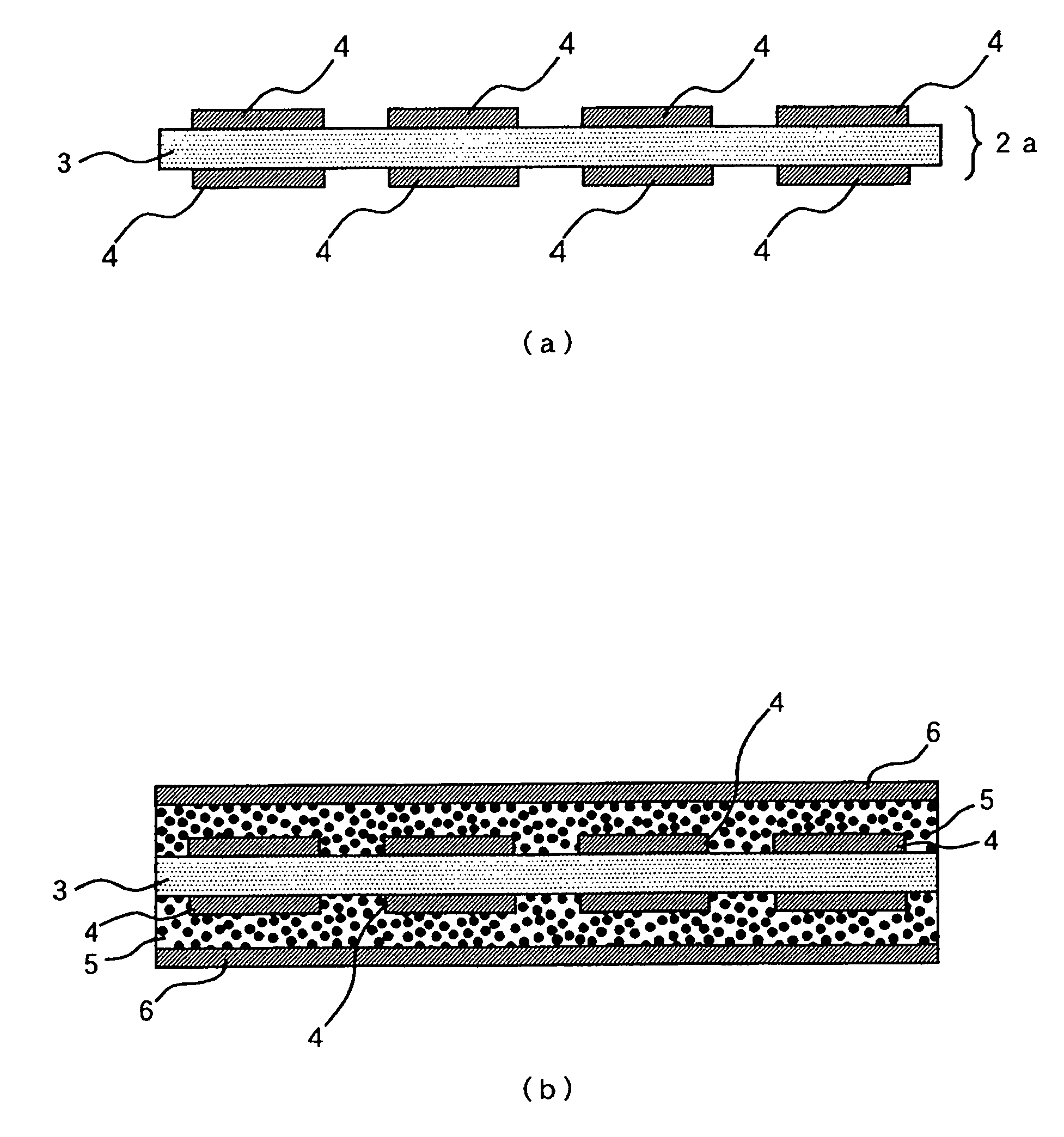
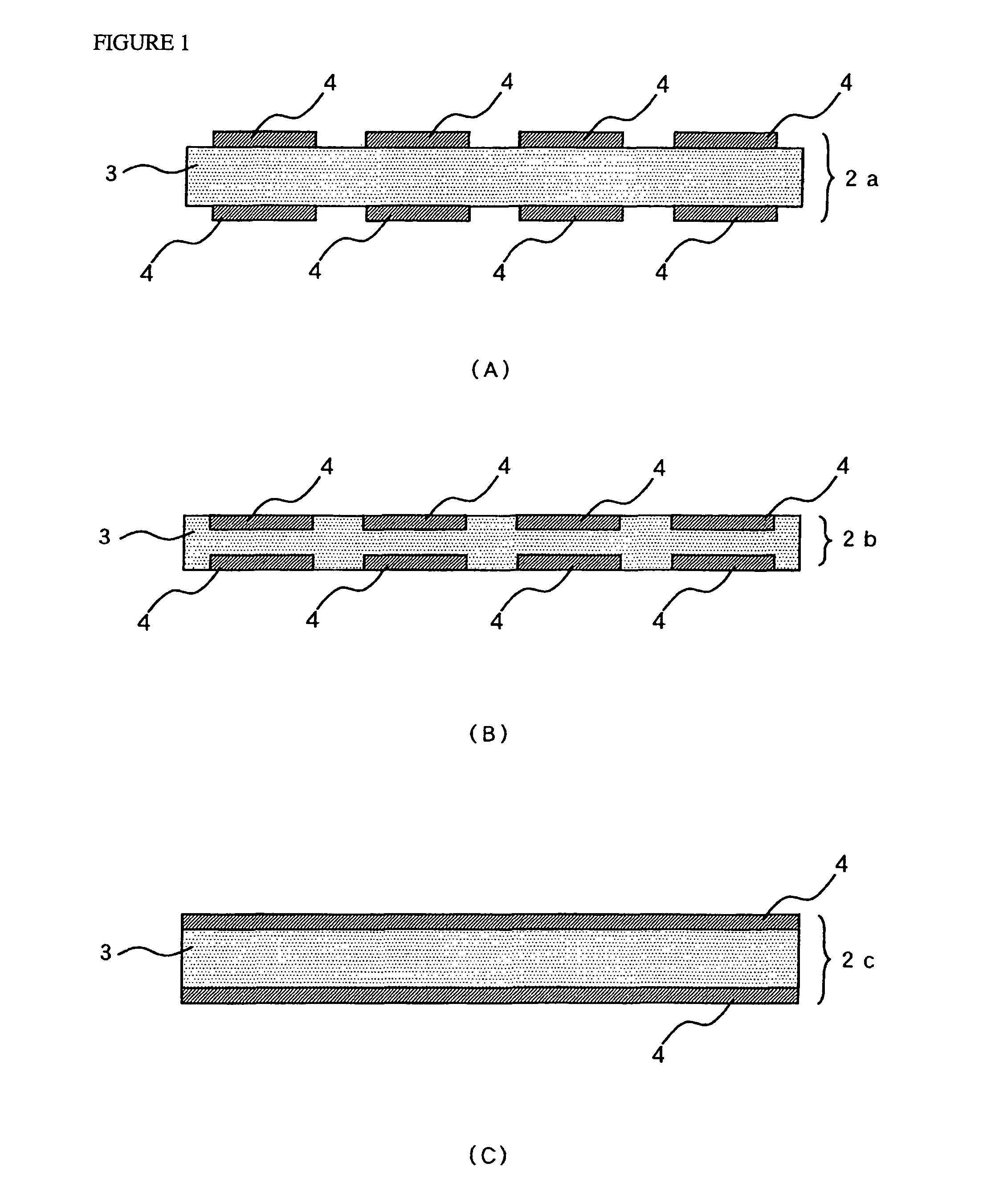
[0102]Based on the popular method, a double sided copper clad laminate was prepared by laminating 18 μm thick electrodeposited copper foil on both sides of a 50 μm thick FR-4 prepreg. The copper foil on both sides of the double sided copper clad laminate was cleaned by polishing and acid pickling, and dried. Then, a dry film resist was laminated on the copper foil on both sides of the laminate, and the etching pattern was exposed on the etching resist and developed. Then, etching was performed with a copper etchant to form base electrode circuits having base electrode shapes. After the resist stripping was performed with an alkaline solution, the laminate was rinsed and dried to obtain a core material.

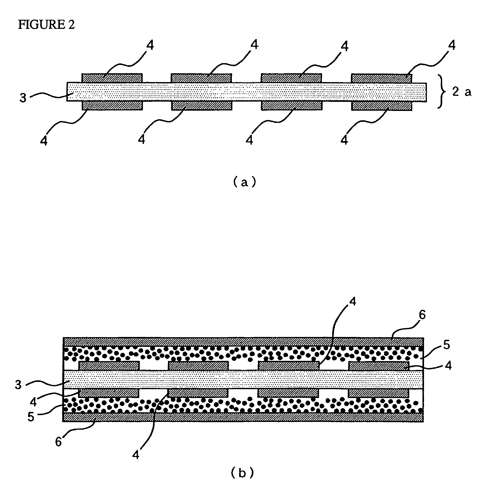
(Preparation of Dielectric Filler Containing Resin Coated Metal Foil)

[0103]First, a resin solution was prepared. In the preparation of the binder resin solution, the raw materials used were 39 parts by weight of phenol novolac type epoxy resin, 39 parts by...

example 2

[0115]Example 2 is the same as Example 1 in step A, step D and step E but different from Example 1 in step B and step C. Accordingly, the description of step A, step D and step E will be omitted to avoid repetition and the description just on step B and step C will be shown.

(Step B)

[0116]In this top-electrode forming step, the first conductive metal layers 6 locating as outer layers were processed into top electrodes 7 of capacitors and the dielectric layers in the area other than those of the circuit portions were exposed. To do this, a dry film resist as an etching resist was laminated on the surface of each first conductive metal layer 6 to give an etching resist layer, the resist pattern is exposed on the etching resist and developed, the unnecessary portion of each first conductive metal layer 6 was dissolved and removed by using an etchant, and the etching resist 10 was allowed to remain on the surface of the circuits even after the top electrodes 7 were formed, as shown in FI...

example 3

(Preparation of Core Material)

[0119]The manufacturing of the core material used in Example 3 will be described with reference to the accompanying drawings. The copper foil circuit with carrier 40 used in this embodiment was obtained by using electrodeposited copper foil with carrier foil 44, which was made by using electrodeposited copper foil having a nominal thickness of 18 μm as carrier foil 41, forming organic bonding interface layer 42 on the shiny side of the carrier foil 41 by using carboxybenzotriazole, and forming copper foil layer for forming circuit 43 having a thickness of 5 μm on the organic bonding interface layer 42. On the copper foil layer for forming circuit 43, fine copper particles 21 are put on its surface. And rust-proofing with zinc on both sides of the electrodeposited copper foil with carrier foil 44 is performed. In the accompanying drawings, the illustration of the rust-proofing layer is omitted.

[0120]A dry film resist was laminated on the surface of the e...


PUM

PropertyMeasurementUnit
particle sizeaaaaaaaaaa
thickaaaaaaaaaa
thickaaaaaaaaaa

Abstract

A method for manufacturing a multilayer printed wiring board which enables the dielectric layers to have excellent thickness uniformity, the capacitor circuits to have high registration accuracy and the unnecessary dielectric layer is removed as large as possible; and a multilayer printed wiring board with an embedded capacitor circuit manufactured by the method.

Description

CROSS REFERENCE TO RELATED APPLICATION[0001]This application is a 35 USC §371 National Phase Entry Application from PCT / JP2005 / 014588, filed Aug. 9, 2005, and designating the United States.TECHNICAL FIELD[0002]The present invention relates to a method for manufacturing a multilayer printed wiring board and a multilayer printed wiring board obtained by the manufacturing method. In particular, the invention provides a suitable method for manufacturing a multilayer printed wiring board with capacitor circuits embedded therein.BACKGROUND ART[0003]Traditionally used multilayer printed wiring boards with capacitor circuits embedded therein are such that one or more of the insulating layers locating in their inner layer(s) is(are) used as a dielectric layer(s) and top electrodes and base electrodes, as capacitors, face each other in the respective inner layer circuits locating on both sides of each dielectric layer. Accordingly, these capacitor circuits are sometimes referred to as embedde...

Claims


Application Information

Patent Timeline
Patent Type & Authority Patents(United States)
IPC IPC(8): C03C15/00
CPCH05K1/162Y10T29/435H05K3/0044H05K3/4626H05K3/4652H05K3/4655H05K2201/0195H05K2201/0209H05K2201/0376H05K2201/09509H05K2203/025H05K2203/0554Y10T29/49155Y10T29/49165Y10T29/4913H05K3/002H05K3/46
Inventor NAKAMURA, KENSUKE
Owner MITSUI MINING & SMELTING CO LTD
Why Eureka
Try Eureka