Method for Manufacturing Multilayer Printed Wiring Board and Multilayer Printed Wiring Board Obtained by the Same
a multi-layer printed wiring board and manufacturing method technology, applied in the direction of variable capacitors, semiconductor/solid-state device details, etching metal masks, etc., can solve the problems of increasing dielectric loss, affecting the registration accuracy of capacitor circuits, and affecting the design of circuits, so as to reduce the occurrence of delamination in the inner layer, the effect of excellent thickness uniformity of the dielectric layer and high registration accuracy
- Summary
- Abstract
- Description
- Claims
- Application Information
AI Technical Summary
Benefits of technology
Problems solved by technology
Method used
Image
Examples
example 1
Preparation of Core Material
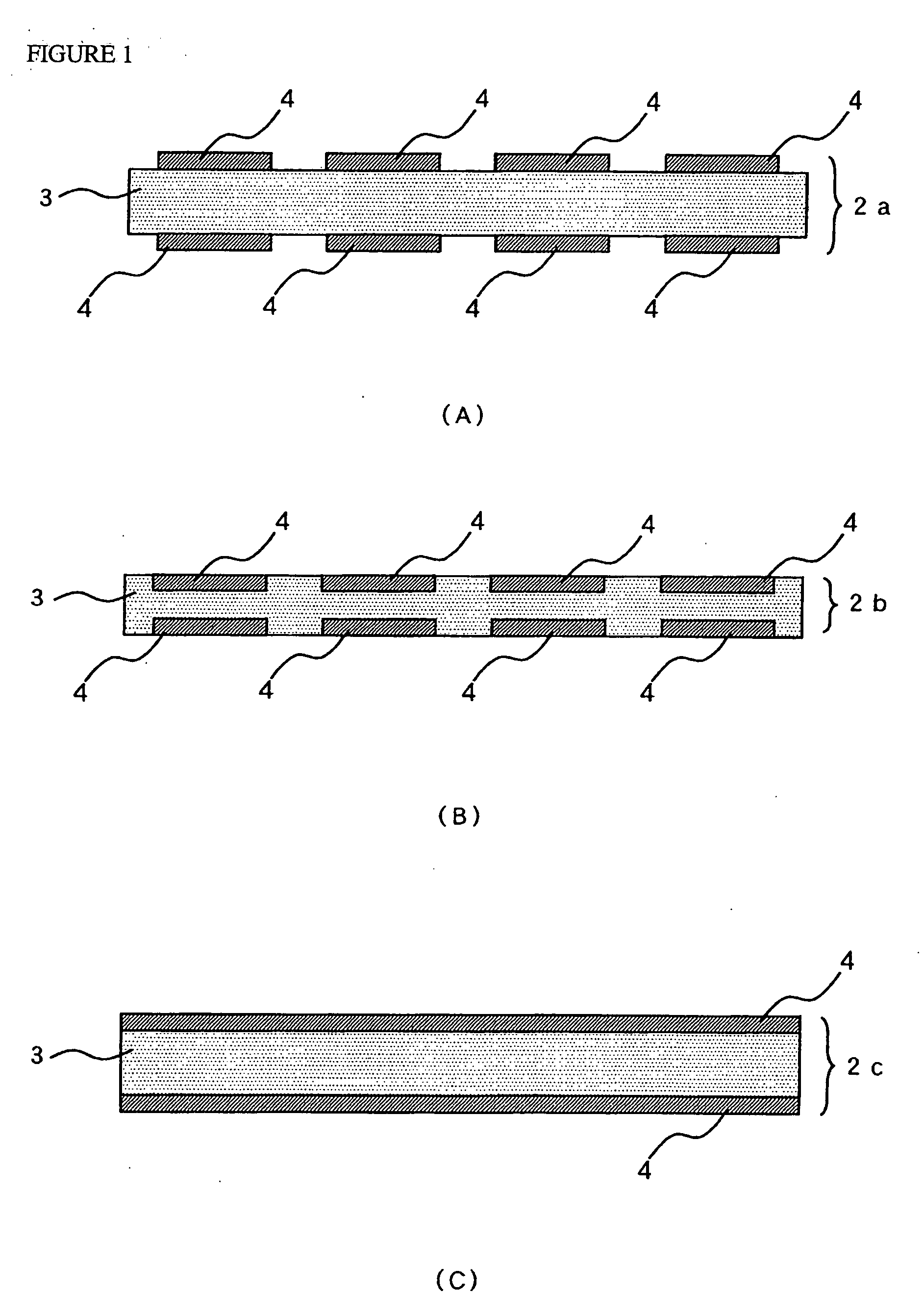
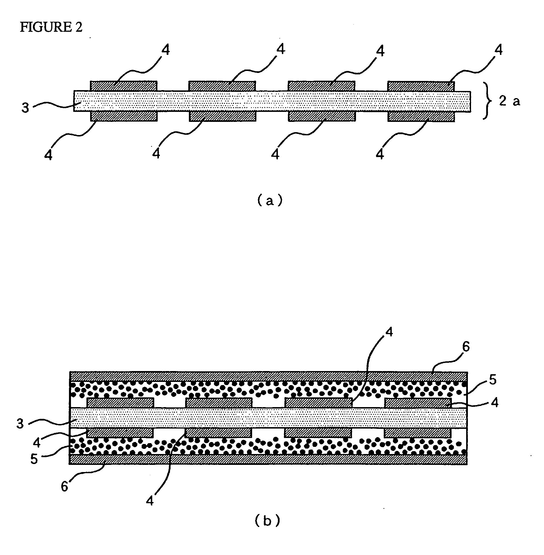
[0113]Based on the popular method, a double sided copper clad laminate was prepared by laminating 18 μm thick electrodeposited copper foil on both sides of a 50 μm thick FR-4 prepreg. The copper foil on both sides of the double sided copper clad laminate was cleaned by polishing and acid pickling, and dried. Then, a dry film resist was laminated on the copper foil on both sides of the laminate, and the etching pattern was exposed on the etching resist and developed. Then, etching was performed with a copper etchant to form base electrode circuits having base electrode shapes. After the resist stripping was performed with an alkaline solution, the laminate was rinsed and dried to obtain a core material.
(Preparation of Dielectric Filler Containing Resin Coated Metal Foil)
[0114]First, a resin solution was prepared. In the preparation of the binder resin solution, the raw materials used were 25 parts by weight of phenol novolac type epoxy resin, 25 parts by w...
example 2
[0125]Example 2 is the same as Example 1 in step A, step D and step E but different from Example 1 in step B and step C. Accordingly, the description of step A, step D and step E will be omitted to avoid repetition and the description just on step B and step C will be shown.
(Step B)
[0126]In this top-electrode forming step, the first conductive metal layers 6 locating as outer layers were processed into top electrodes 7 of capacitors and the dielectric layers in the area other than those of the circuit portions were exposed. To do this, a dry film resist as an etching resist was laminated on the surface of each first conductive metal layer 6 to give an etching resist layer, the resist pattern is exposed on the etching resist and developed, the unnecessary portion of each first conductive metal layer 6 was dissolved and removed by using an etchant, and the etching resist 10 was allowed to remain on the surface of the circuits even after the top electrodes 7 were formed, as shown in FI...
example 3
Preparation of Core Material
[0129]The manufacturing of the core material used in Example 3 will be described with reference to the accompanying drawings. The copper foil circuit with carrier 40 used in this embodiment was obtained by using electrodeposited copper foil with carrier foil 44, which was made by using electrodeposited copper foil having a nominal thickness of 18 μm as carrier foil 41, forming organic bonding interface layer 42 on the shiny side of the carrier foil 41 by using carboxybenzotriazole, and forming copper foil layer for forming circuit 43 having a thickness of 5 μm on the organic bonding interface layer 42. On the copper foil layer for forming circuit 43, fine copper particles 21 are put on its surface. And rust-proofing with zinc on both sides of the electrodeposited copper foil with carrier foil 44 is performed. In the accompanying drawings, the illustration of the rust-proofing layer is omitted.
[0130]A dry film resist was laminated on the surface of the ele...
PUM
| Property | Measurement | Unit |
|---|---|---|
| particle size | aaaaa | aaaaa |
| thick | aaaaa | aaaaa |
| thick | aaaaa | aaaaa |
Abstract
Description
Claims
Application Information
 - R&D
- Intellectual Property
- Life Sciences
- Materials
- Tech Scout
- Unparalleled Data Quality
- Higher Quality Content
- 60% Fewer Hallucinations
Browse by: Latest US Patents, China's latest patents, Technical Efficacy Thesaurus, Application Domain, Technology Topic, Popular Technical Reports.
© 2025 PatSnap. All rights reserved.Legal|Privacy policy|Modern Slavery Act Transparency Statement|Sitemap|About US| Contact US: help@patsnap.com


