
Method of driving liquid flow at or near the free surface using magnetic microparticles

Inactive Publication Date: 2011-10-11
THE UNITED STATES AS REPRESENTED BY THE DEPARTMENT OF ENERGY
View PDF10 Cites 6 Cited by
  • Summary
  • Abstract
  • Description
  • Claims
  • Application Information

AI Technical Summary

Benefits of technology

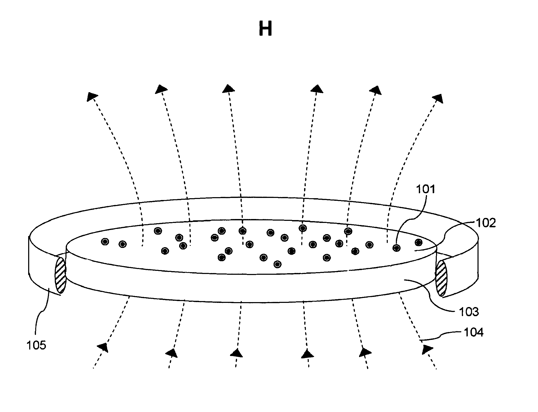
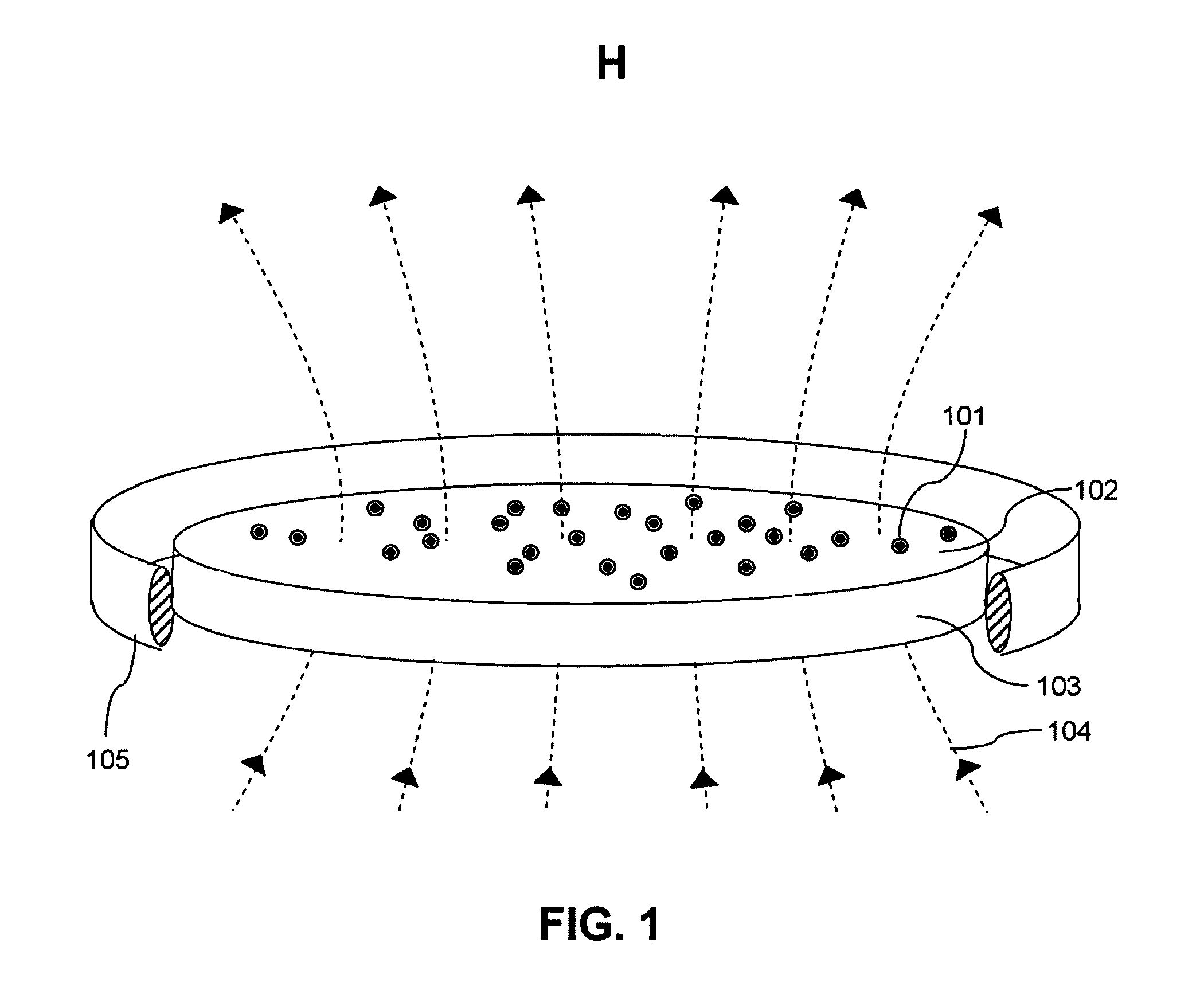
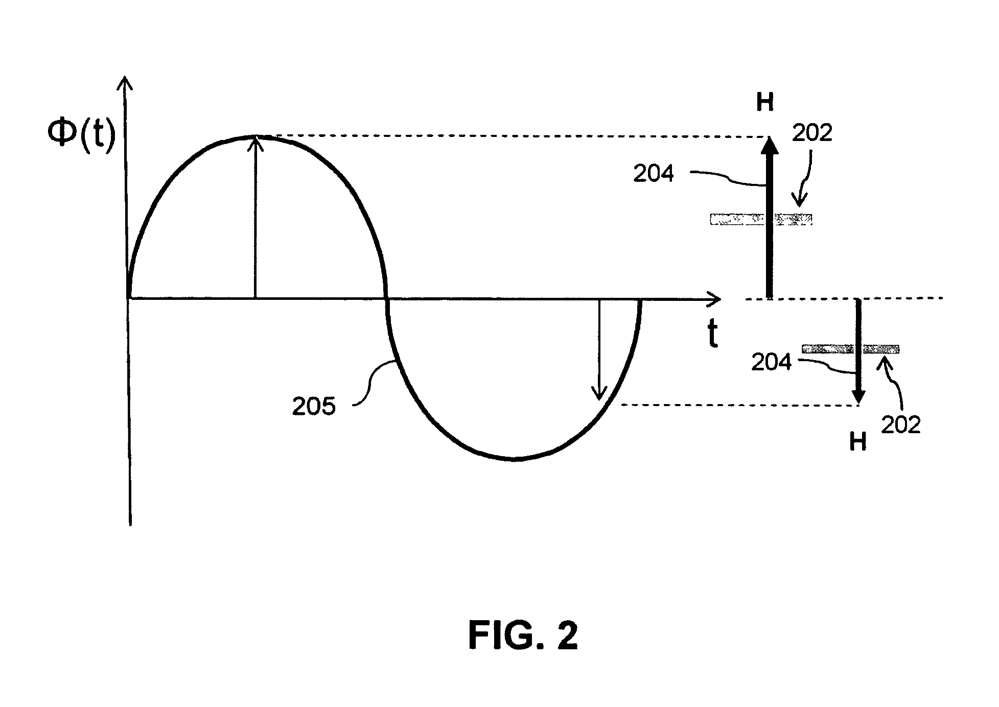
[0011]The snake structures exhibit harmonic oscillation with the frequency of the magnetic field and drive unstable temporary liquid vortices, effectuating liquid flow over essentially the entirety of the free surface. The method may be utilized to drive liquid flow in order to mix one or more materials by adding materials to the liquid such that the temporary liquid vortices produce mixing. The method may also be utilized in order to separate one or more materials by providing magnetic particles treated to act as a capture moiety and adding a target agent to the liquid, such that the temporary liquid vortices create proximity between the capture moiety and the target agent and a binding reaction occurs. The method may also be used to reduce transfer resistances at or near the free surface of the liquid, or in other various processes which may be aided by liquid agitation. The method has advantage in that it does not rely on magnetic dipole moment alignment between magnetic particles and externally applied magnetic field lines to produce magnetic particle motion, and does not require either complex physical apparatus in order to physically relocate the magnetic field source or the medium, or, in the case of an electromagnet, intricate timing mechanisms to vary input power in a predetermined manner. This method can utilize a simple sinusoidal AC magnetic field from an AC magnetic field source which remains stationary relative to the medium containing the magnetic particles. Further, the method produces self-assembled structures independently moving across the liquid surface, driving liquid flow across essentially the entirety of the liquid surface to essentially eliminate dead flow areas.

Problems solved by technology

A drawback to these methods is the requirement for essentially continuous alternation of the relative spatial orientation between the external magnetic field lines and the medium, which requires either complex physical apparatus in order to physically relocate the magnetic field source or the medium, or, in the case of an electromagnet, intricate timing mechanisms to vary input power in a predetermined manner.
Additionally, since the liquid agitation rate in these systems depends directly on the rate at which the relative spatial orientation can be altered, any complex physical apparatus relied on to physically relocate the AC magnetic field source or the medium fades severe limitation as the rate is increased.
As a result, they retain the drawback of requiring either complex physical apparatus in order to physically relocate the magnetic field source or the medium, or, in the case of an electromagnet, intricate timing mechanisms to vary input power in a predetermined manner.
However, Snezhko, et al., limits his discussion to low frequency regimes where self-assembled structures oscillate around essentially stationary points on the free surface, producing stable liquid vortices with dead flow areas outside the vortices where mixing is severely compromised.

Method used


Image

  • Method of driving liquid flow at or near the free surface using magnetic microparticles
  • Method of driving liquid flow at or near the free surface using magnetic microparticles
  • Method of driving liquid flow at or near the free surface using magnetic microparticles

Examples


Embodiment Construction

[0024]The following description is provided to enable any person skilled in the art to use the invention and sets forth the best mode contemplated by the inventor for carrying out the invention. Various modifications, however, will remain readily apparent to those skilled in the art, since the principles of the present invention are defined herein specifically to provide a method for generating liquid flow at or near a free surface of a liquid using magnetic particles subject to an AC magnetic field. The liquid flow so generated may be useful for mixing heterogeneous components; facilitating chemical and biological reactions, reducing transfer resistances at or near the free surface of the liquid, and conducting other processes aided by liquid agitation.

[0025]The expression “free surface” referred to herein is meant to include a liquid surface where the pressure on the liquid surface is equal to an external pressure acting outside the bulk of the liquid. The free surface may occur a...


PUM

PropertyMeasurementUnit
Diameteraaaaaaaaaa
Diameteraaaaaaaaaa
Diameteraaaaaaaaaa

Abstract

The present invention provides a method of driving liquid flow at or near a free surface using self-assembled structures composed of magnetic particles subjected to an external AC magnetic field. A plurality of magnetic particles are supported at or near a free surface of liquid by surface tension or buoyancy force. An AC magnetic field traverses the free surface and dipole-dipole interaction between particles produces in self-assembled snake structures which oscillate at the frequency of the traverse AC magnetic field. The snake structures independently move across the free surface and may merge with other snake structures or break up and coalesce into additional snake structures experiencing independent movement across the liquid surface. During this process, the snake structures produce asymmetric flow vortices across substantially the entirety of the free surface, effectuating liquid flow across the free surface.

Description

RELATION TO OTHER APPLICATIONS[0001]This patent application is a continuation-in-part and claims priority to U.S. patent application Ser. No. 11 / 641,337 filed Dec. 19, 2006, submitted by Snezhko et al., now U.S. Pat. No. 7,875,187 B2, which is hereby incorporated by reference in its entirety.STATEMENT OF GOVERNMENTAL SUPPORT[0002]The United States Government has rights in this invention pursuant to Contract No. DE-AC02-06CH11357 between the U.S. Department of Energy and UChicago Argonne, LLC.TECHNICAL FIELD[0003]A method of driving liquid flow utilizing magnetic particles dispersed on or near the free surface of the liquid and subjected to an external AC magnetic field oriented such that the magnetic field lines traverse the free surface of the liquid. The magnetic particles experience strong dipole-to-dipole attractions sufficient to overcome magnetic torques acting to align the magnetic particles with the external AC magnetic field, and form a multiplicity of snake structures lyin...

Claims


Application Information

Patent Timeline
IPC IPC(8): B01D35/06
CPCB03C1/0335B03C1/288B03C2201/18
Inventor SNEZHKO, OLEKSIYARONSON, IGORKWOK, WAI-KWONGBELKIN, MAXIM V.
Owner THE UNITED STATES AS REPRESENTED BY THE DEPARTMENT OF ENERGY
Learn More