
Land-based electric vehicle charging plug

a charging plug and electric vehicle technology, applied in the direction of charging stations, transportation and packaging, charging devices, etc., can solve the problems of high degree of faulty implementation, and high degree of wear of the charging plug, so as to achieve simple and reliable electrical contact exchange

Active Publication Date: 2019-07-18
DR ING H C F PORSCHE AG
View PDF16 Cites 4 Cited by
  • Summary
  • Abstract
  • Description
  • Claims
  • Application Information

AI Technical Summary

Benefits of technology

This patent describes a land-based electric vehicle charging plug that has reliable and easy-to-use electrical contacts. The plug has a funnel-shaped design that allows for a certain amount of rotational inaccuracy when attaching a new interface to the plug. This reduces damage to the charging contacts and ensures consistent functionality even when replacing the interface multiple times. Additionally, the plug has stabilizing lug bodies that help prevent lateral impacts on the interface, protecting the charging contacts from damage.

Problems solved by technology

In contrast to the vehicle-based charging plug, the land-based charging plug is subjected to a high degree of wear since it is used, that is to say is coupled and decoupled, several hundred times up to several thousand times per year.
In addition to pure wear of the electrical contacts, the charging plug is moreover also subjected to mechanical loading and possibly mechanically damaged, for example due to falling and hitting the ground.
This method is laborious and very susceptible to faulty implementation since the quality of the charging plug overhauled in this way is very dependent on the care taken by the technician.
If the contacts which correspond to one another are not in exact axial alignment with one another during the plugging-on operation, the plugging-together operation is very difficult.
Furthermore, the meeting contact ends of the adapter contacts and of the corresponding base contacts can be deformed or damaged in the event of poor alignment during the plugging-together operation.
If the contacts are charging current contacts, poor contact-connection can lead to excessive heating at high charging currents owing to the relatively high non-reactive resistance.

Method used


Image

  • Land-based electric vehicle charging plug
  • Land-based electric vehicle charging plug
  • Land-based electric vehicle charging plug

Examples


Embodiment Construction

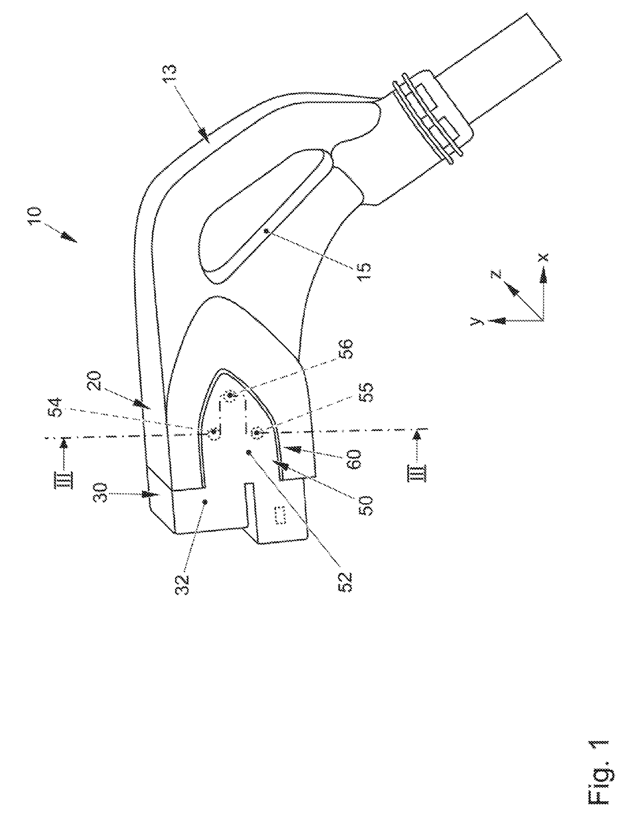
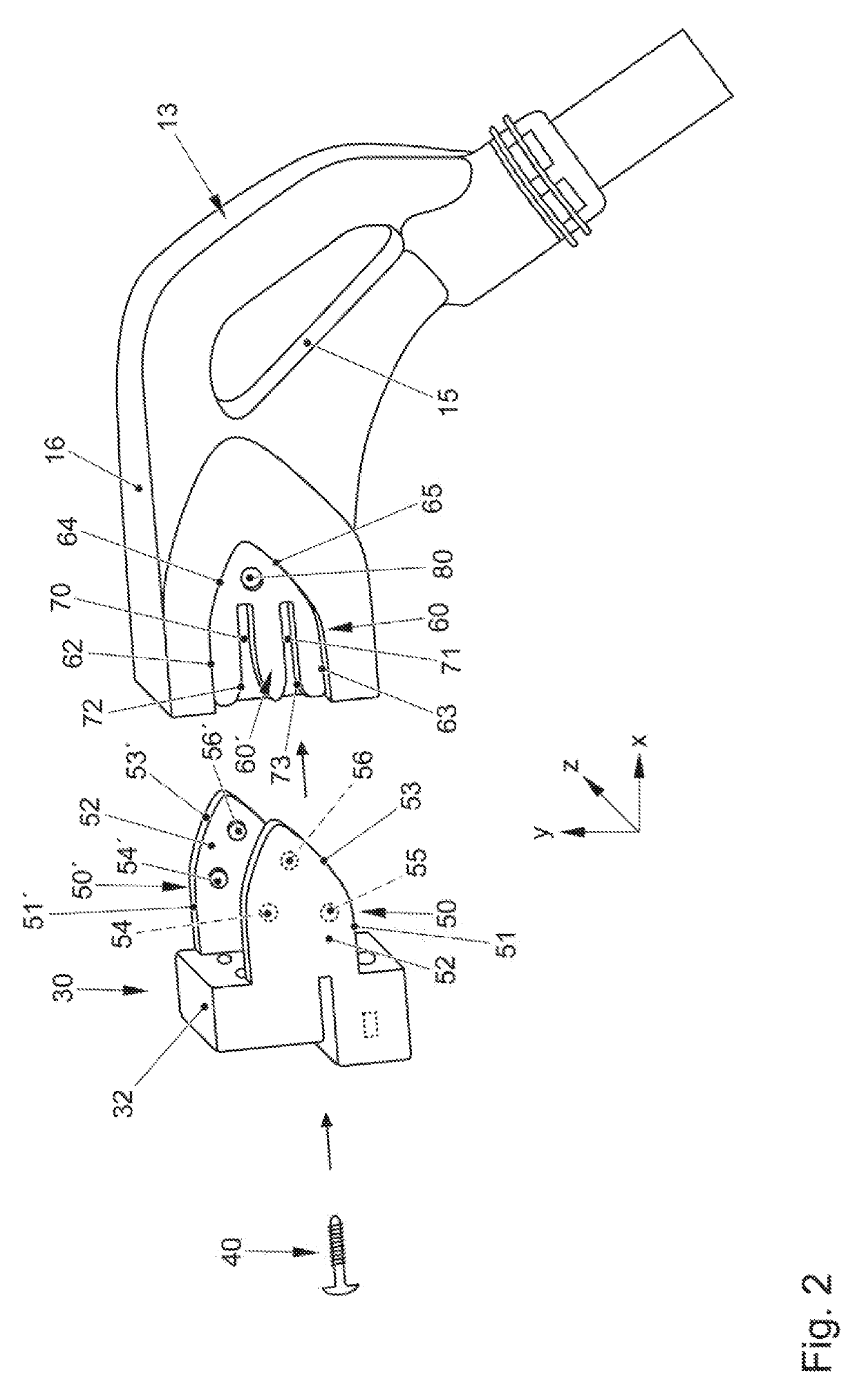
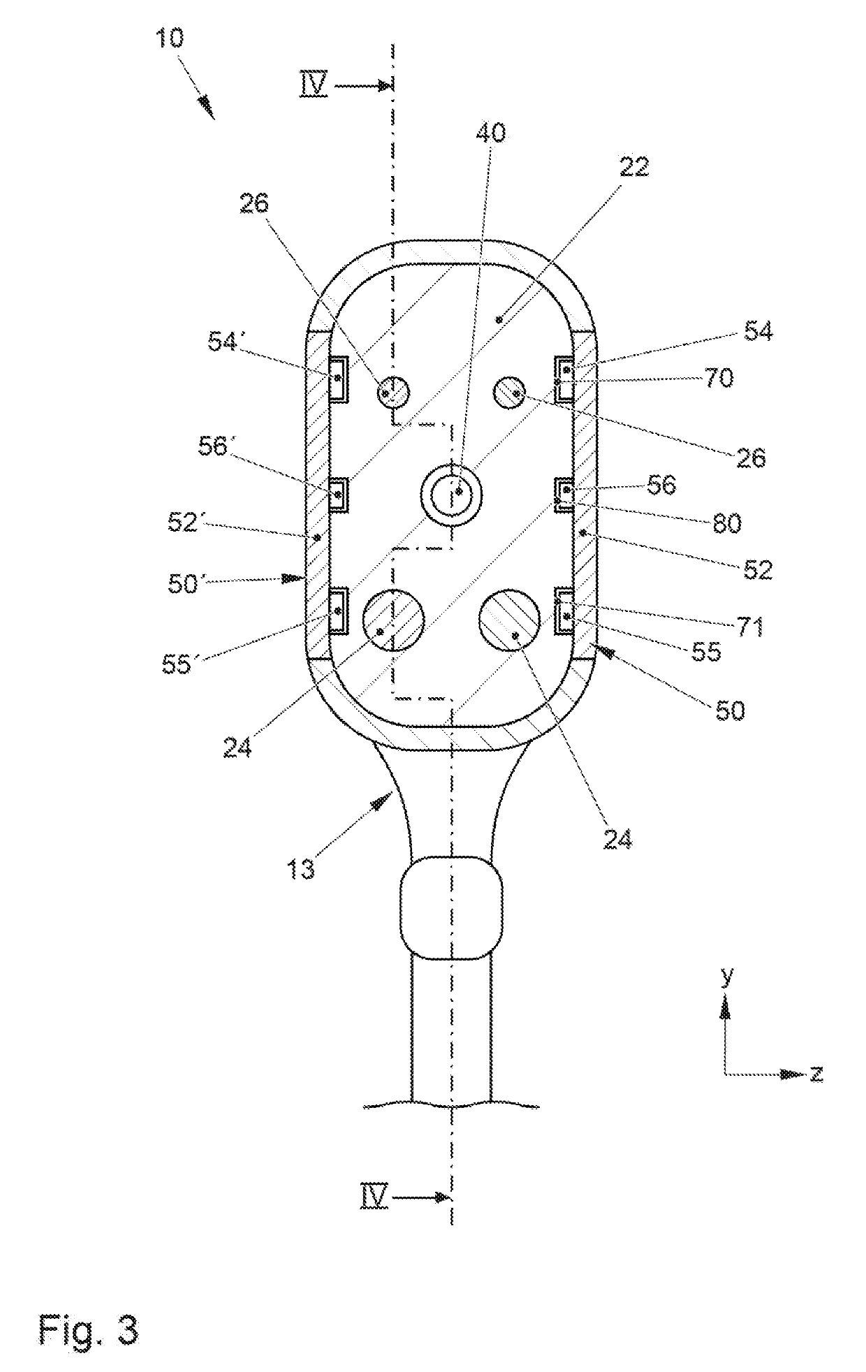
[0029]FIGS. 1, 3 and 4 illustrate an assembled land-based electric vehicle charging plug 10 which is suitable for being plugged into a corresponding vehicle-based charging plug (not illustrated) in order to charge a traction battery of an electric vehicle. The charging plug 10 has a grip part 13 which is formed by a grip part housing 16 and defines a grip opening 15 which can be grasped by the hand of an operator.

[0030]A plug base 20 is fixedly anchored at the distal end of the grip part housing 16. The plug base 20 is formed by an electrically non-conductive plastic base body 22 and two charging current base contacts 24 which are fixedly anchored in the base body 22 and two signal base contacts 26. All of the base contacts 24, 26 are fixedly anchored in the base body 22 in such a way that they cannot be removed from the base body 22 without damaging or without destroying the base body 22.

[0031]The plug base 20 remains on the grip part housing 16 over the entire lifetime of the char...


PUM


Abstract

A land-based electric vehicle charging plug has a plug base and a separate and exchangeable interface which is detachably fastened to the plug base. The plug base has an electrically non-conductive base body and at least one charging current base contact. The interface has an electrically non-conductive interface body and at least one charging current interface contact which is plugged-together with the corresponding charging current base contact. The plug base and the interface have a positive guide which forms an insertion funnel.

Description

CROSS-REFERENCE TO RELATED APPLICATION[0001]This application claims priority to German Patent Application No. DE 10 2018 100 825.2, filed Jan. 16, 2018, which is incorporated by reference herein in its entirety.FIELD OF THE INVENTION[0002]The invention relates to a land-based electric vehicle charging plug which can be plugged into a vehicle-based charging plug for the purpose of charging a vehicle-based traction battery.BACKGROUND OF THE INVENTION[0003]The land-based electric vehicle charging plug is part of a land-based charging station for charging a traction battery of an electric vehicle. In contrast to the vehicle-based charging plug, the land-based charging plug is subjected to a high degree of wear since it is used, that is to say is coupled and decoupled, several hundred times up to several thousand times per year. In addition to pure wear of the electrical contacts, the charging plug is moreover also subjected to mechanical loading and possibly mechanically damaged, for ex...

Claims


Application Information

Patent Timeline
Patent Type & Authority Applications(United States)
IPC IPC(8): H01R31/06B60L53/16H01R27/00H01R13/512
CPCH01R31/06B60L53/16H01R27/00H01R13/512H01R2201/26H01R13/631H01R13/6215H01R13/502H01R13/506H01R13/629Y02T10/70Y02T90/14Y02T10/7072
Inventor GOTZ, STEFANRONFANZ, JARIREBER, VOLKER
Owner DR ING H C F PORSCHE AG
Learn More