
Method for continuity test of integrated circuit

a continuity test and integrated circuit technology, applied in continuity testing, instruments, measurement devices, etc., can solve the problems of inability to refer, abnormal test results, failure to meet the requirements of reference, etc., and achieve the effect of more precise test results

Active Publication Date: 2011-10-04
KING YUAN ELECTRONICS
View PDF12 Cites 1 Cited by
  • Summary
  • Abstract
  • Description
  • Claims
  • Application Information

AI Technical Summary

Benefits of technology

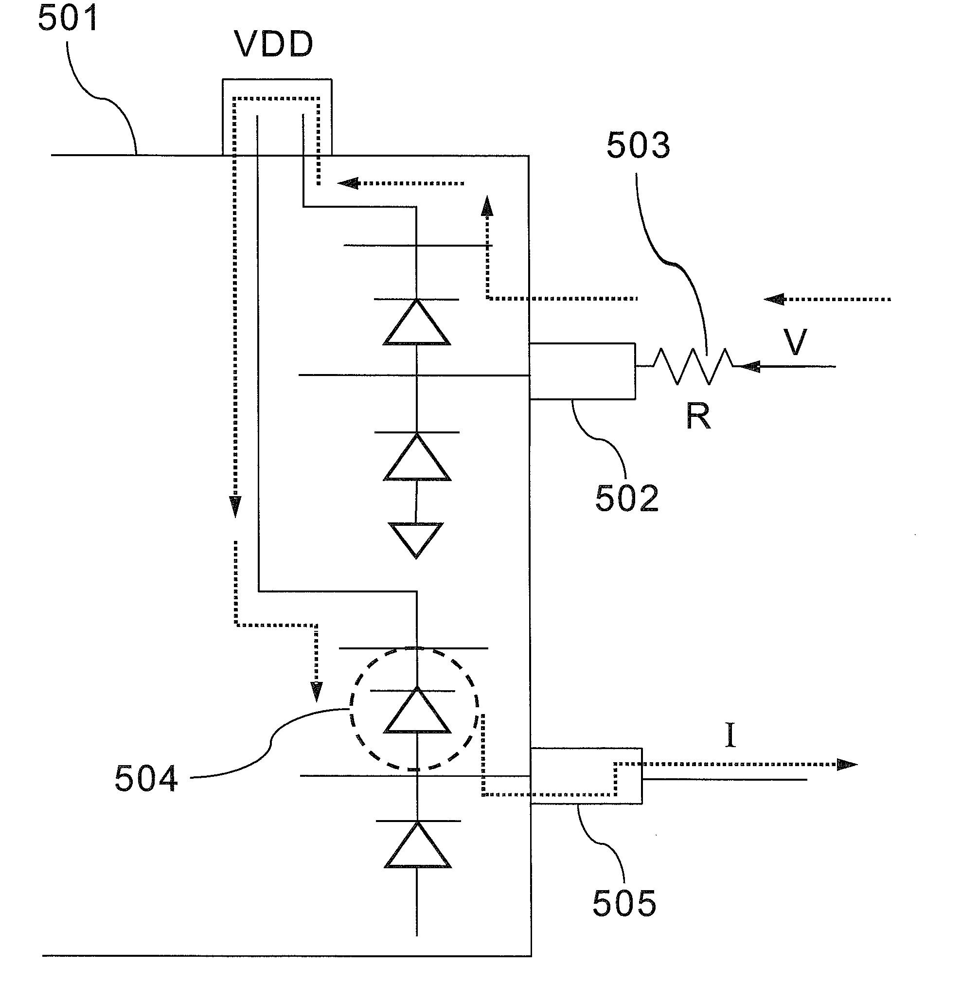
[0009]To achieve the object mentioned above, the present invention provides a method for testing integrated circuit (IC), which comprises a current of an ESD device of the IC is measured by using two pins of the IC for obtaining a contact resistance of the IC. The method of the present invention comprises following steps: First, a DUT is provided, and the DUT includes a second pin connecting to a zero reference potential. Then, a voltage is applied to a first pin of the DUT. Finally, a current through the first pin and the second pin could be measured. Furthermore, a contact resistance of the DUT could be calculated by the voltage and the current. Therefore, the testing result of the DUT could be more precise and the quality of the DUT would be made sure.
[0010]Thus, the method of the present invention for continuity test of IC could solve the problem that resistance of IC can't be measured by conventional technology. Moreover, the method of the present invention improves the problem that contact resistance of IC can't be measured accurately and quality of the DUT would be made sure.

Problems solved by technology

Otherwise, outside the mentioned-above ranges, the test result of the DUT is unacceptable and shown fail for reference.
However, a DUT having a 900Ω contact resistance would make the DUT be judged being abnormal when functional test of the DUT is performed.
Then, the whole quality of the DUT would be affected by judging error.

Method used


Image

  • Method for continuity test of integrated circuit
  • Method for continuity test of integrated circuit
  • Method for continuity test of integrated circuit

Examples


Embodiment Construction

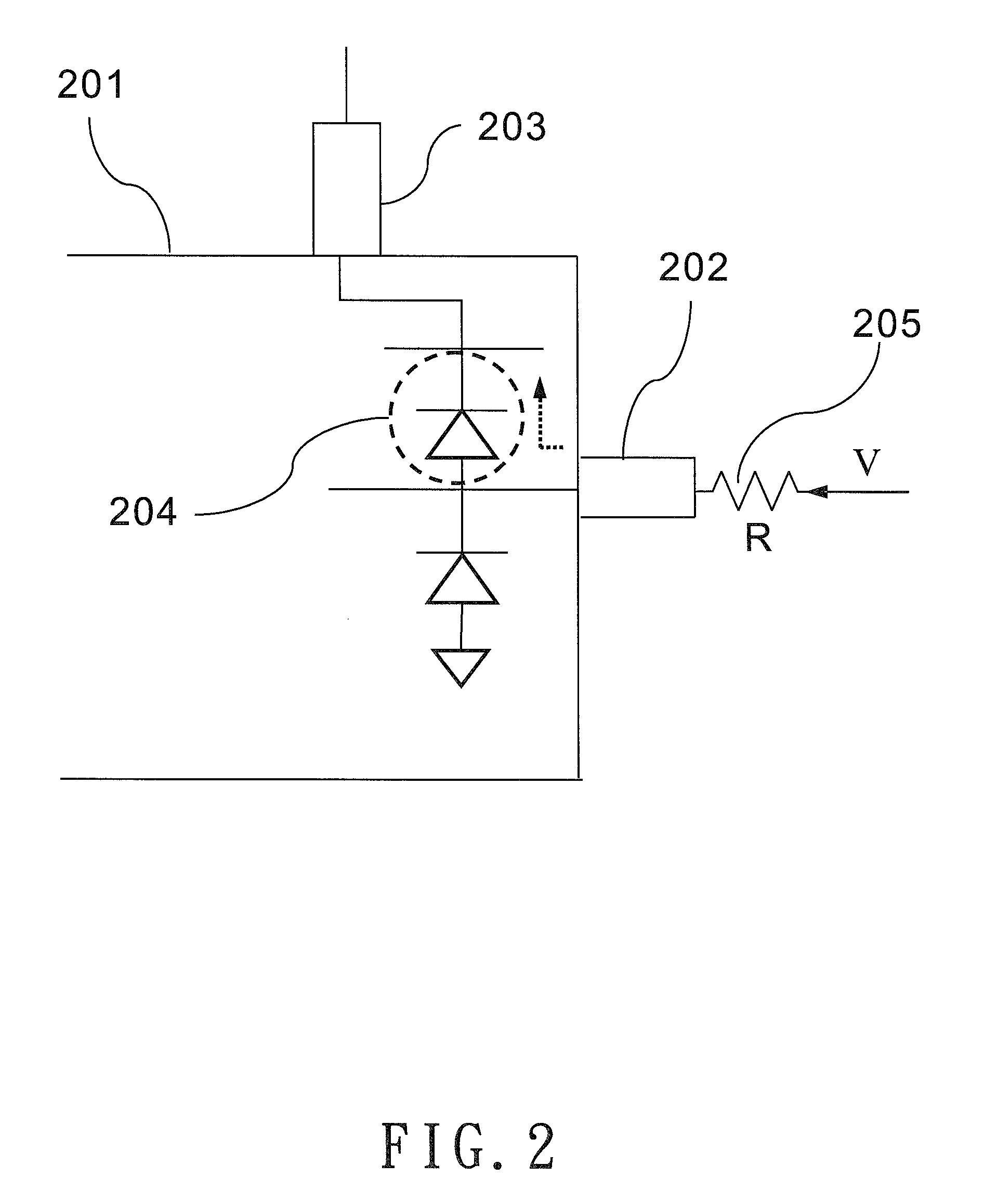
[0019]FIG. 2 shows a diagram of a method of the present invention for testing integrated circuit (IC). In FIG. 2, a device under test (DUT) 201 has a first pin 202, a second pin 203 and an electrostatic discharge device (ESD) 204. FIG. 3 shows a flowchart of the method of the present invention for testing IC, and accompanies with FIG. 2 to describe the method of the present invention as below:

[0020]In step S301, it shows providing a DUT 201. The DUT 201 could be one selected from following: such as memory, system on chip (SOC), drive chip of LCD, charge coupled device (CCD), mixed signal IC, or RF IC etc.

[0021]In step S302, it shows connecting a second pin 203 of the DUT 201 to ground. The purpose of connecting the second pin 203 to ground is to form a test circuit after applying a voltage to the DUT 301. Then, this step would advantage the following current measurement.

[0022]In step S303, it shows applying a voltage to a first pin 202 of the DUT 201. Then, a current would be formed...


PUM


Abstract

The present invention provides a method for continuity test of integrated circuit. By using both pins of integrated circuit to measure a current of an electrostatic discharge device, the contact resistance of the integrated circuit can be obtained by calculating. The method comprises the steps: First, a DUT (device under test) is provided, and the DUT includes a second pin and the second pin connecting zero reference potential. Then, a voltage is applied to a first pin of DUT. Finally, the current through said first pin and said second pin would be measured. Therefore, the testing result of the DUT could be more precise and the quality of the DUT would be made sure.

Description

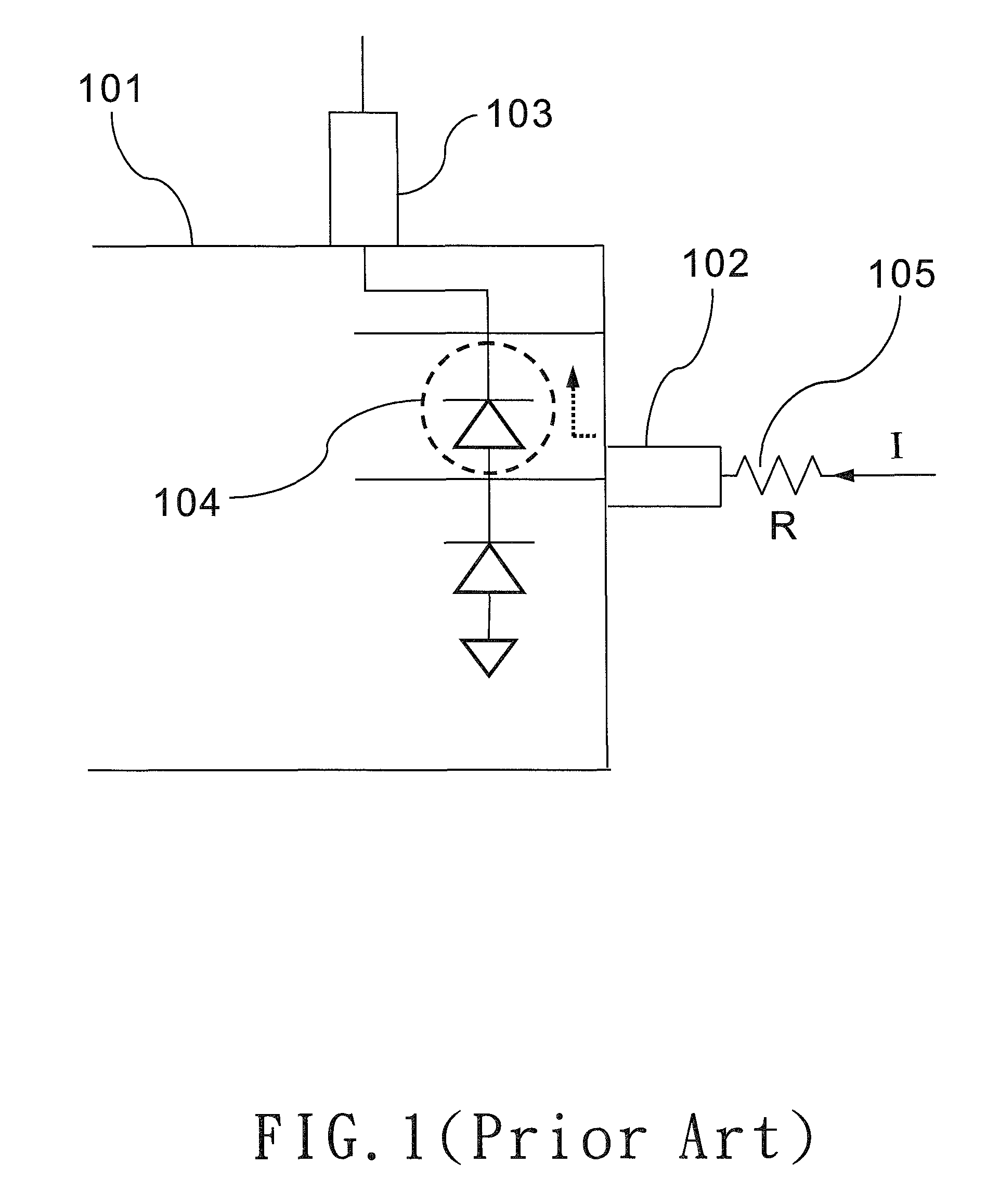
BACKGROUND OF THE INVENTION[0001](1) Field of the Invention[0002]The present invention relates to a method for continuity test of integrated circuit. More particularly, the present invention relates to a method for continuity test of integrated circuit by utilizing current flow.[0003](2) Prior Art[0004]Integrated circuit (IC) is a device which is formed a complete and logical circuit by integrating several electronic devices, such as transistor, electrostatic discharge device (ESD), and capacitor etc., on a silicon chip. Integrated circuits could have several abilities of function, such as control, calculate, and memory etc., for applying varies of electronic products. Fabrication process of integrated circuit includes design, pulling, slicing, polishing, oxidation, diffusion, deposition, mask, etching, detection, die saw, die bonding, wire bonding, package, test process etc. In these processes, the test process is to test several characteristics of integrated circuit, such as elect...

Claims


Application Information

Patent Timeline
IPC IPC(8): G01R31/02G01R31/28
CPCG01R31/2853G01R31/026G01R31/54
Inventor NI, CHENG-CHIN
Owner KING YUAN ELECTRONICS
Learn More