
Combined iris imager and wavefront sensor

a wavefront sensor and imager technology, applied in the field of iris imaging, can solve the problems of significant processing requirements, and achieve the effect of fast reading and maximum image quality

Inactive Publication Date: 2011-09-27
TASCENT INC
View PDF50 Cites 56 Cited by
  • Summary
  • Abstract
  • Description
  • Claims
  • Application Information

AI Technical Summary

Benefits of technology

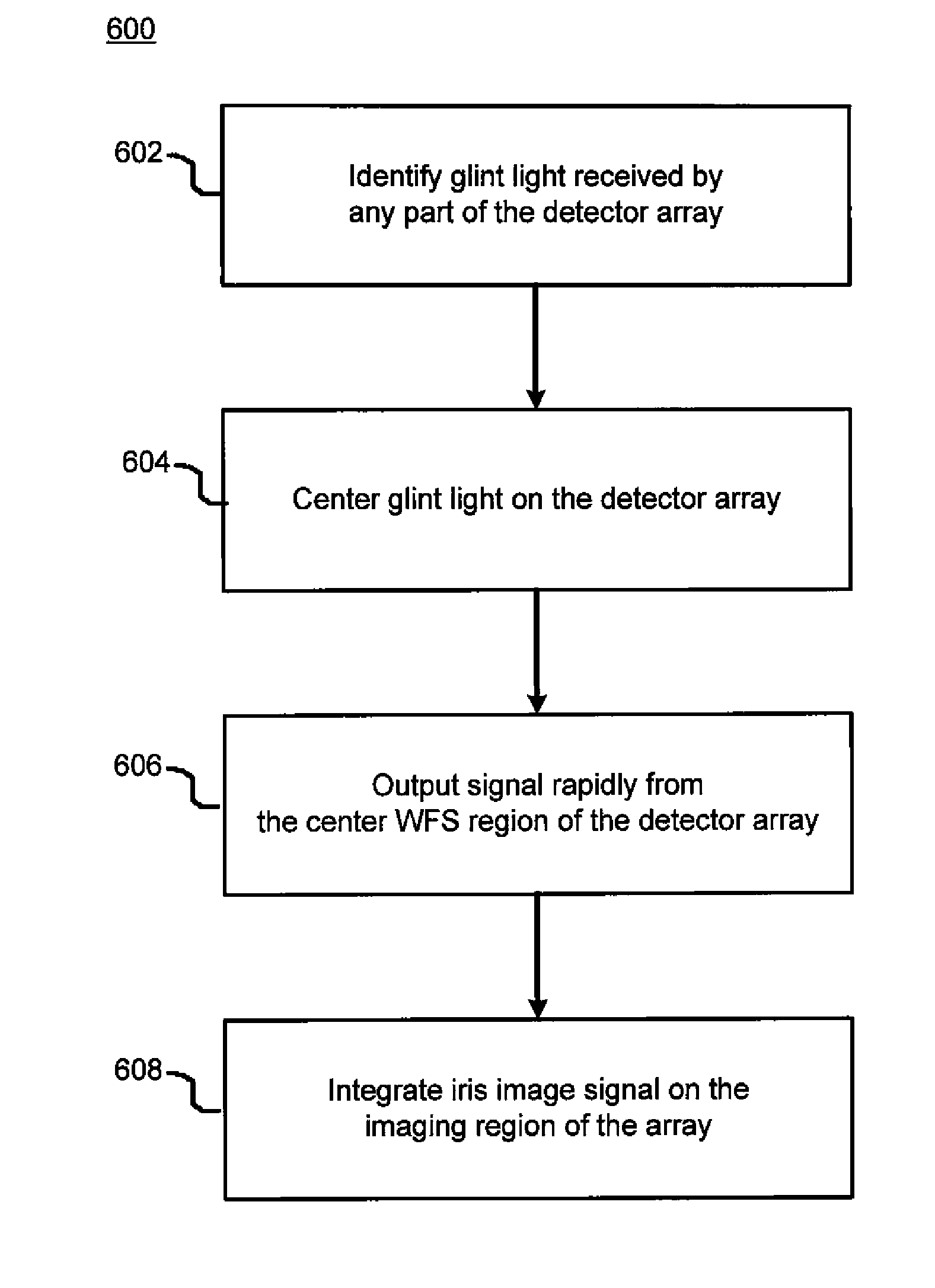
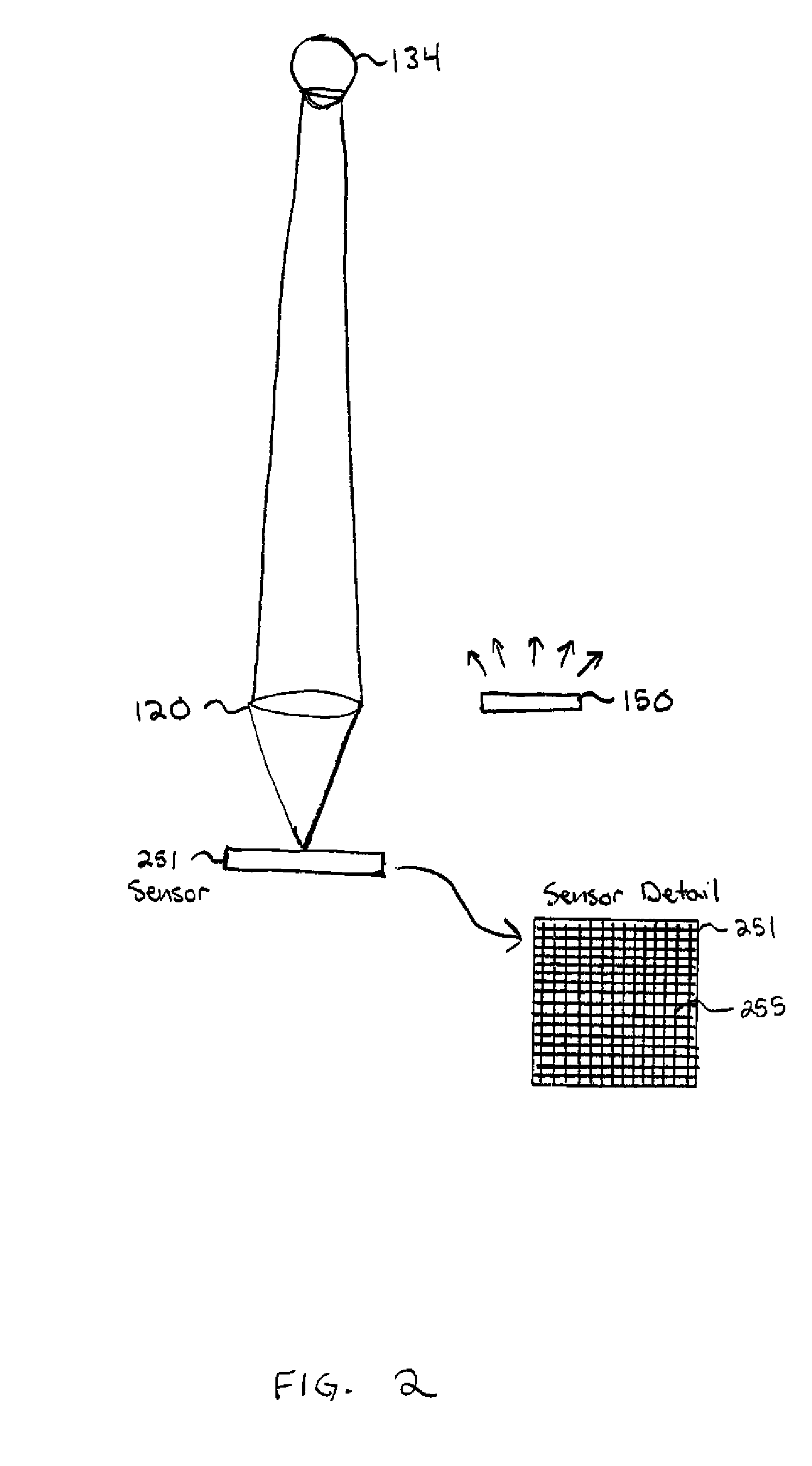
[0008]The present invention provides an iris imaging system for biometric identification having a combined iris imager and wavefront sensor. In one embodiment, the same detector array can be used for both iris imaging and wavefront sensing at the image plane. The detector allows for independent readout of different regions, such that the WFS region can be read out fast while allowing signal to integrate on the iris imaging portions of the detector array. Alternatively, the entire array may be used for wavefront sensing during an acquisition phase, and then a portion of the array may be switched to be used for iris imaging during a subsequent imaging phase. A single detector may also switch between wavefront sensing mode and imaging mode, so that image quality can be maximized before each image capture exposure.
[0009]In one embodiment, an optical periscope allows various optics to be inserted in front of the iris imager and wavefront sensor in order to realize some forms of WFS functionality. Examples of the optics that may be inserted via the optical periscope include a curvature sensor or phase diversity sensor using a birefringent lens, and a beam splitter arrangement to achieve a curvature sensor or phase diversity sensor by forming two adjacent images of different focus. Other forms of WFS can also be implemented using the periscope technique. In addition, a simple phase diversity sensor can be built by inserting a known additional phase aberration in the glint path. For detection of the simple aberrations of tip-tilt and focus, no additional optics is required, since these aberrations may easily be measured in the image plane. The ability to independently read out the WFS section of the array at high frame rates is very useful. In principle higher order aberrations can also be detected in the image plane, but the processing requirements are significant.
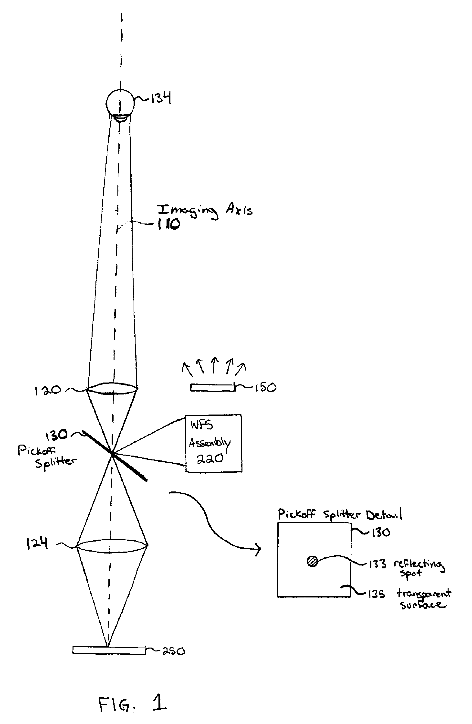
[0010]In another embodiment, the glint image of an on-axis or near on-axis illumination source is reflected from the central portion of the pupil of the eye so as to be spatially isolated in the image plane. The glint light from the pupil field is picked off at the image plane and directed to the wavefront sensor optics, while allowing all of the light from the iris field to pass through to the iris imaging camera. This arrangement may use separate image and WFS detectors, but the WFS pickoff is performed efficiently in or near the image plane.

Problems solved by technology

In principle higher order aberrations can also be detected in the image plane, but the processing requirements are significant.

Method used


Image

  • Combined iris imager and wavefront sensor
  • Combined iris imager and wavefront sensor
  • Combined iris imager and wavefront sensor

Examples


Embodiment Construction

[0020]Traditionally, it has been thought that a large angle between the illumination direction and the optical axis of the iris imaging camera is necessary to improve the contrast of images. This was assumed to be due to the three-dimensional structure of the iris. However, experiments conducted by the inventors have shown that the iris image contrast is not significantly reduced by using on-axis or near on-axis illumination.

[0021]An advantage of on-axis or near on-axis illumination is that the camera and illuminator can be housed in a single package, which makes deployment of the system much easier and its use more convenient. A further benefit of on-axis or near on-axis illumination is that the glint from the iris illuminator source will be positioned within the eye pupil, and will not contaminate the area of the iris image available for coding.

[0022]As has been described in U.S. patent application Ser. No. 11 / 765,401, filed Jun. 19, 2007, entitled “Iris Imaging Using Reflection F...


PUM


Abstract

An iris imaging system used for biometric identification provides a combined iris imager and wavefront sensor. The detector array allows for independent readout of different regions, such that a wavefront sensor region can be read out fast while allowing signal to integrate on the iris imaging region. Alternatively, the entire array may be used for wavefront sensing during an acquisition phase, and then at least a portion of the array may be switched to be used for iris imaging during a subsequent imaging phase. An optical periscope optionally allows various optics to be inserted in front of the combined iris imager and wavefront sensor. In another embodiment, the glint image of an on-axis or near on-axis illumination source is picked off at the image plane and directed to the wavefront sensor optics, while allowing all of the light from the iris field to pass through to the iris imaging camera.

Description

CROSS-REFERENCE TO RELATED APPLICATION(S)[0001]This application claims priority from U.S. Provisional Patent Application Ser. No. 60 / 886,890, filed Jan. 26, 2007, entitled “Combined Iris Imager and Wavefront Sensor.” This application is related to U.S. patent application Ser. No. 11 / 765,401, filed Jun. 19, 2007, entitled “Iris Imaging Using Reflection From The Eye,” and U.S. patent application Ser. No. 11 / 297,578, filed on Dec. 7, 2005, entitled “Iris Imaging Using Reflection From The Eye.” The subject matter of all of the foregoing is incorporated herein by reference in their entirety.BACKGROUND OF THE INVENTION[0002]1. Field of the Invention[0003]This invention relates to iris imaging, as may be used for biometric identification.[0004]2. Description of the Related Art[0005]A biometric iris imaging sensor can rapidly deliver more consistently high quality images by incorporating tip-tilt (tracking) and focus correction. At very long standoff distances, or under adverse conditions, ...

Claims


Application Information

Patent Timeline
Patent Type & Authority Patents(United States)
IPC IPC(8): A61B3/00
CPCG06K9/00604G06V40/19
Inventor NORTHCOTT, MALCOLM J.GRAVES, J. ELON
Owner TASCENT INC
Learn More